Integrated Wireless Video Surveillance Solution for Tunnel and Pipeline Construction
Solution Background
Tunnel pipeline construction scenarios are characterized by **enclosed environments, long and narrow spaces, high mobility of construction points, and high difficulty in cabling**. Traditional wired video monitoring systems suffer from problems such as long construction cycles, high modification costs, and inability to adapt to the mobile operations of engineering vehicles, making it difficult to meet the requirements for real-time, comprehensive, and flexible monitoring during the construction process. To ensure the safety of tunnel construction and improve construction management efficiency, combined with the actual scenario of the 1.5km tunnel construction, this wireless video monitoring solution is formulated. By building a stable, efficient, and practical wireless monitoring system using industrial-grade wireless transmission equipment, it achieves visualized management of the full construction scene.
Core Objectives
- Achieve **7×24 hour real-time video monitoring** of the entire tunnel construction area (both tunnel entrances, mobile engineering vehicles, and inside the tunnel) with no monitoring blind spots;
- Adapt to the mobile operation needs of engineering vehicles, ensuring stable transmission of wireless signals from mobile monitoring points with no lagging or disconnection;
- Support local management at the monitoring center + remote access via mobile/PC, realizing flexibility and convenience in construction management;
- Feature video recording, playback, and PTZ control functions to provide data support for construction safety tracing and accident investigation;
- System construction balances **practicality, cost-effectiveness, and scalability**, adapting to the complex on-site environment of tunnel construction with low implementation difficulty.
I. Overall System Architecture Design
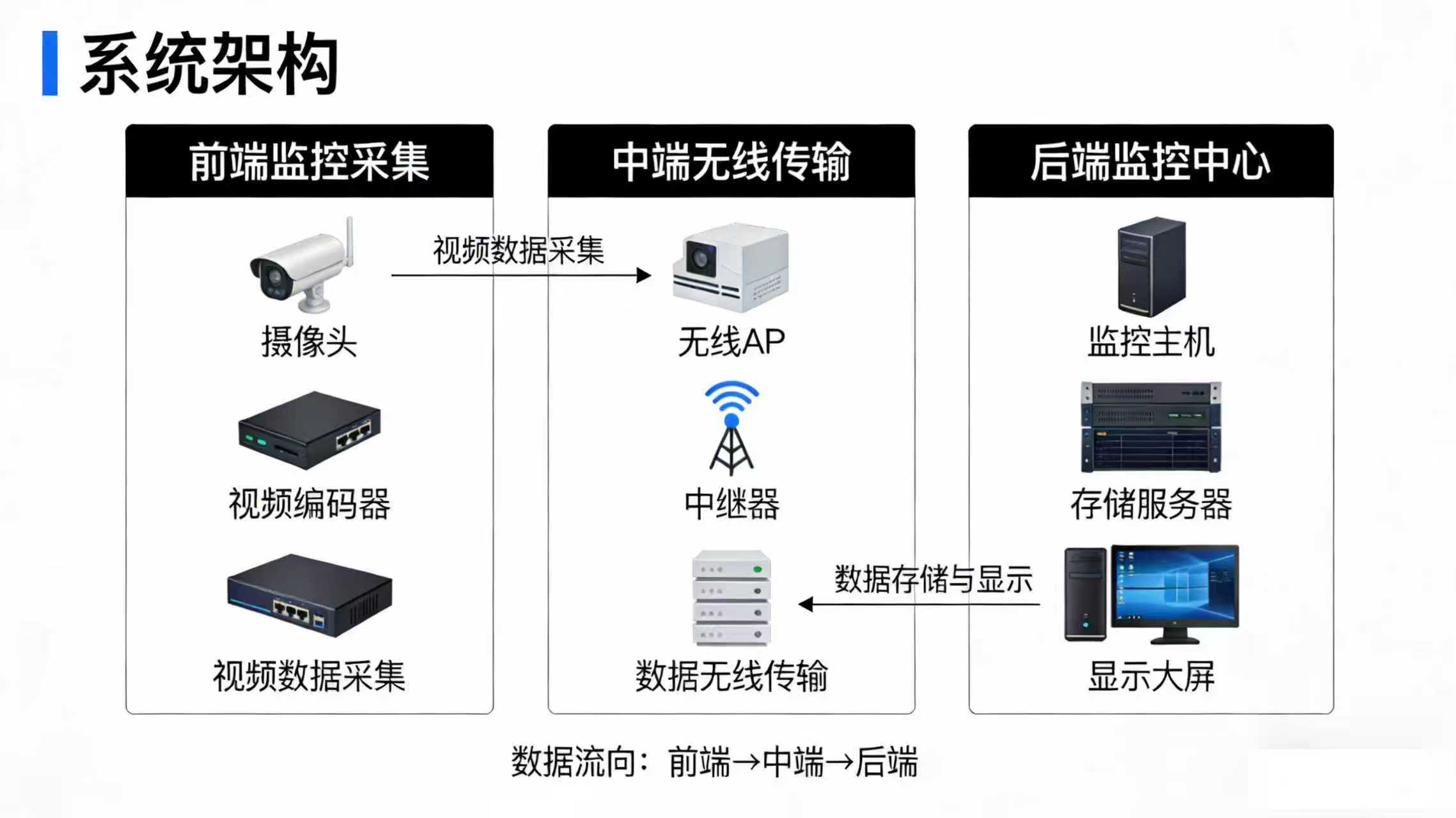
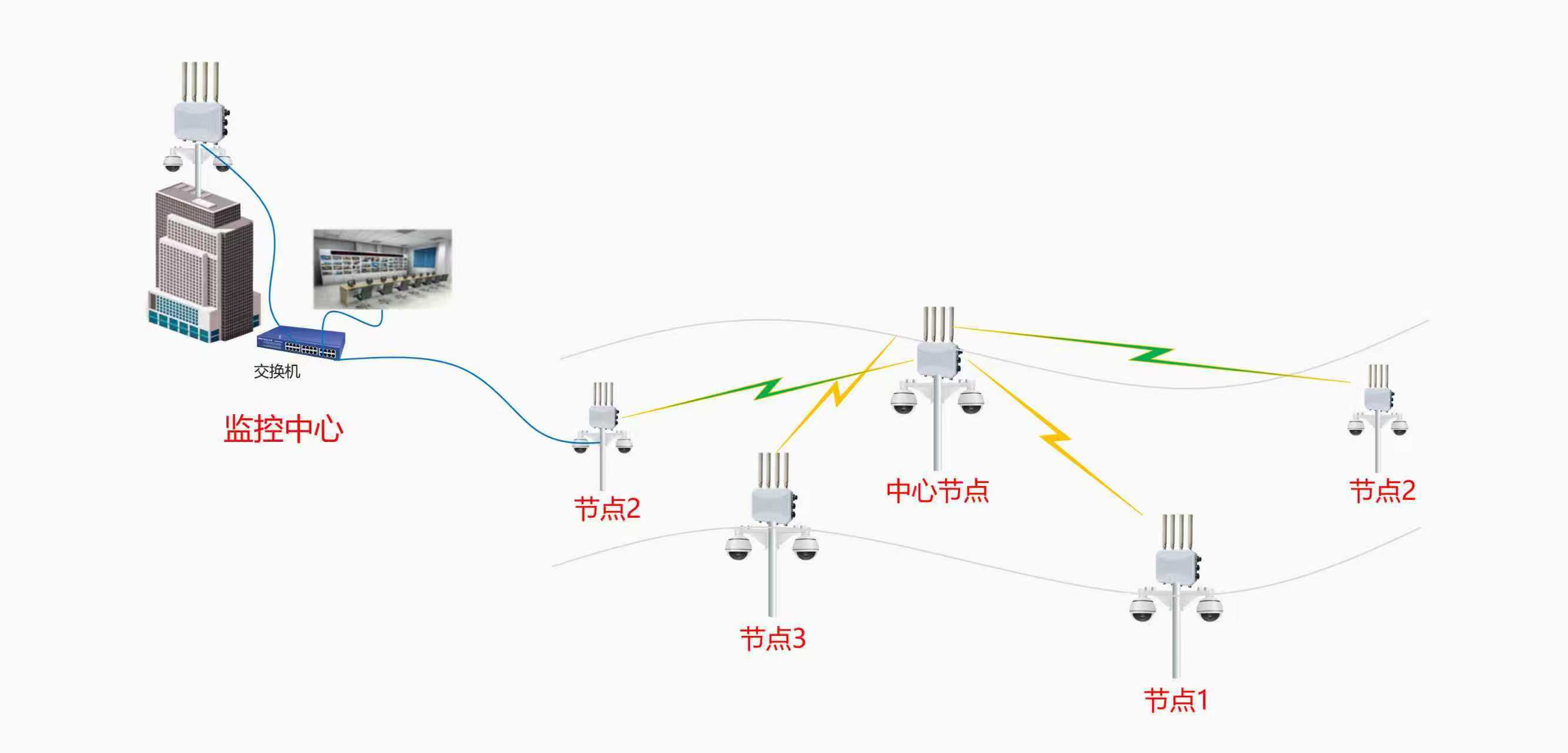
This tunnel pipeline construction wireless video monitoring system adopts a **three-tier architecture** design, consisting of **Front-end Monitoring Data Collection**, **Mid-end Wireless Transmission**, and **Back-end Data Storage & Control**. These three parts work synergistically to achieve a closed loop from video collection and wireless transmission to data processing, storage, and display. The overall system architecture is shown below:
System Architecture Diagram
II. Detailed Design and Implementation
(I) Front-end Monitoring Data Collection Part
1. Monitoring Point Planning
Combined with the actual needs of the 1.5km tunnel construction, a total of **8 monitoring points** are planned, configured with **7 network cameras** (some points share equipment to maximize coverage). The specific point distribution is as follows:
| Monitoring Point | Equipment Configuration | Monitoring Range & Purpose | Installation Requirements |
|---|---|---|---|
| Right Tunnel Entrance | 2 Network Cameras | Covers right tunnel entrance/exit channel, construction material area | Mounted on entrance pole, height 3-5m |
| Engineering Vehicle 1 | 2 Network Cameras | Covers engineering vehicle operation face, surrounding construction area | Mounted on vehicle front/rear, anti-vibration |
| Engineering Vehicle 2 | 2 Network Cameras | Covers engineering vehicle operation face, surrounding construction area | Mounted on vehicle front/rear, anti-vibration |
| Left Tunnel Entrance (Monitoring Center) | 1 Network Camera | Covers monitoring center perimeter, left tunnel entrance/exit channel | Mounted on center outer wall, facing tunnel |
2. Equipment Selection Requirements
- Adopt **HD Network Cameras**, resolution not less than 1080P, meeting detail monitoring needs;
- Adapt to **low light, high dust** tunnel environments, selecting IR night vision, IP66 waterproof/dustproof rated equipment;
- Vehicle cameras must possess **anti-vibration, anti-bump** characteristics to adapt to mobile operation scenarios;
- Support PTZ control functions for remote adjustment of shooting angle and focal length, realizing flexible monitoring range adjustment.
3. On-site Implementation Points
- All cameras connected to the nearest switch via **Cat5e cables**, with conduit protection to avoid damage;
- Vehicle cameras equipped with vehicle power adapters for stable power supply, adding power protection devices against voltage fluctuations;
- After installation, debug shooting angles one by one to ensure no blind spots and clear, unobstructed views.
(II) Mid-end Wireless Transmission Part
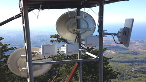
This part is the core of the system, solving the transmission problem of non-line-of-sight (NLOS) due to tunnel curvature. It uses **industrial-grade wireless bridges** as core equipment, combined with relay points to achieve signal relay transmission, ensuring stable and high-speed video signal transmission throughout.
1. Core Transmission Equipment Selection
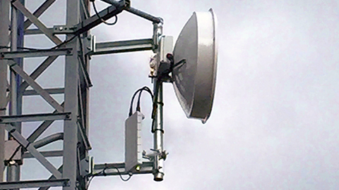
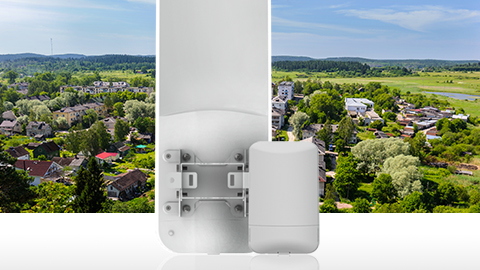
Mainly select **Industrial-grade Wireless Bridge** + Omni-directional Antenna. Core parameters and advantages:
| Equipment Parameter | Specific Specs | Advantages for Tunnel Construction |
|---|---|---|
| Working Frequency | 5GHz | Avoids 2.4GHz civilian interference, more stable transmission |
| Transmission Technology | 2×2 MIMO Technology | Enhances signal penetration and transmission distance |
| Max Bandwidth | 300Mbps | Satisfies simultaneous multi-channel HD video transmission without lag |
| Device Characteristics | Industrial-grade Design | Dustproof, waterproof, high/low temp resistance, adapts to harsh tunnel environment |
| Supporting Antenna | Omni-directional Antenna | 360° signal coverage, adapts to mobile transmission of engineering vehicles |
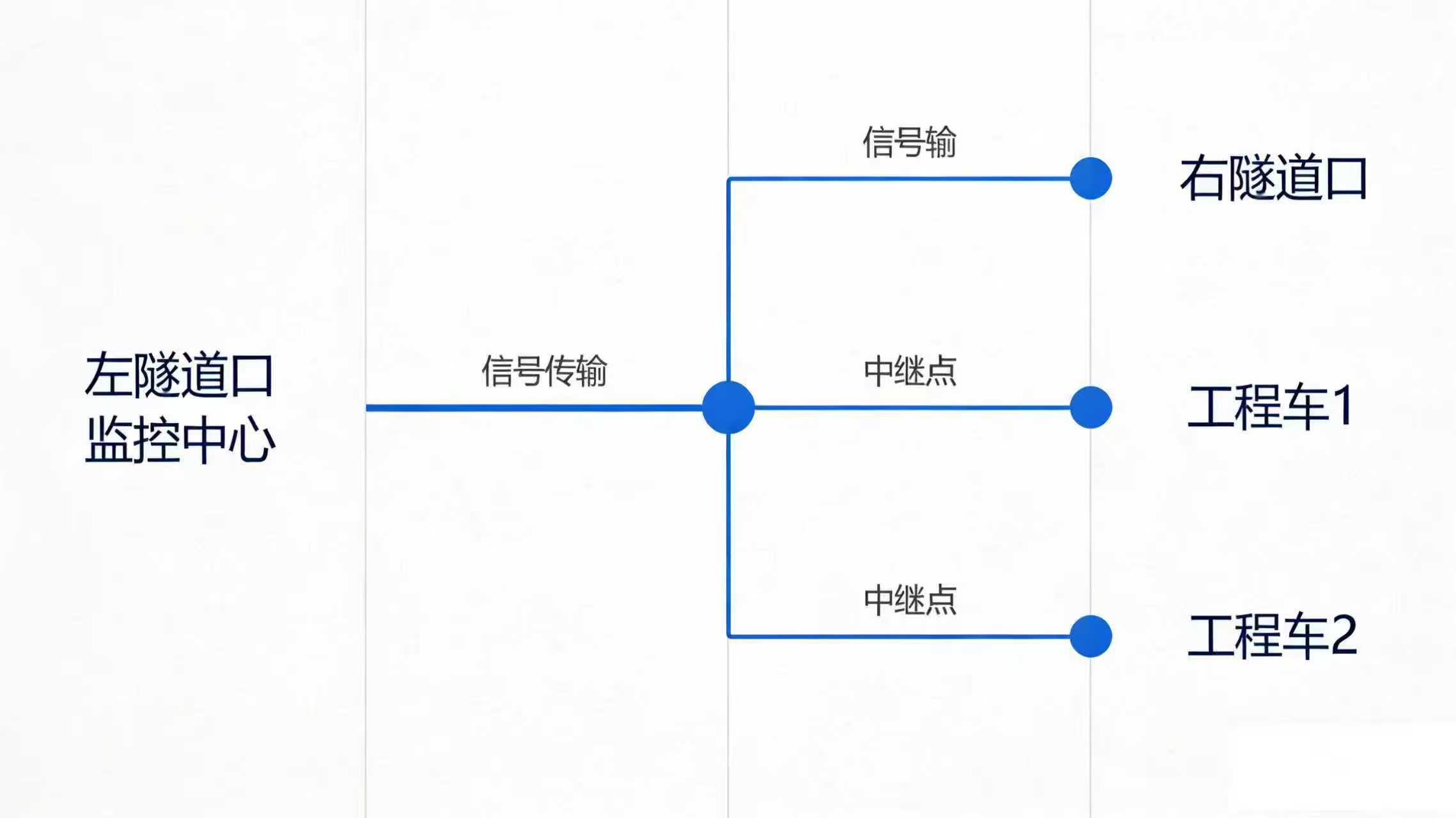
2. Wireless Transmission Topology Design
Since the tunnel is not straight and the transmitter and receiver cannot be in line-of-sight (LOS) without obstruction, a **relay point is established at the tunnel turn**, adopting a **Transmit – Relay – Receive** relay transmission mode. The specific topology and implementation are as follows:
3. Branch Transmission Implementation Details
Branch 1: Right Tunnel Entrance Signal Transmission
- The 2 cameras at the right tunnel entrance are connected to **1 Fast Ethernet Switch** via network cable to complete signal integration;
- The switch connects to **1 Wireless Bridge (Transmitter)**, transmitting signals to the relay point;
- The relay point deploys **1 Wireless Bridge (Receiver)** specifically to receive signals from the right tunnel entrance.
Branch 2: Engineering Vehicle 1 Signal Transmission
- The 2 cameras on Engineering Vehicle 1 integrate signals via the onboard switch;
- Connects to **1 DLB11ax Wireless Bridge + Omni-directional Antenna (Transmitter)** to achieve mobile signal transmission;
- The relay point deploys **1 DLB11ax Wireless Bridge + Omni-directional Antenna (Receiver)** to receive the mobile signal from Engineering Vehicle 1, with the omni-antenna ensuring no signal disconnection during vehicle movement.
Branch 3: Engineering Vehicle 2 Signal Transmission
Completely consistent with Engineering Vehicle 1, transmitting signals via **Onboard Switch + DLB11ax + Omni-directional Antenna**, received by the same model equipment + omni-antenna at the relay point.
Relay Point Signal Aggregation and Retransmission
- The relay point aggregates the signals from the 3 receiving devices and connects them to **1 Core Switch** for signal integration;
- The core switch connects to **1 DLB11ax Wireless Bridge (Master Transmitter)**, transmitting the aggregated multi-channel video signals to the monitoring center at the left tunnel entrance.
4. Relay Point On-site Implementation Requirements
- The relay point is selected at a position with **relatively open field of view** at the tunnel turn, installed on a fixed bracket on the tunnel side wall at a height of 2.5-3 meters;
- The relay point is equipped with a **Waterproof Distribution Box**, housing the switch and power adapter, with dustproof, waterproof, and anti-smash protection;
- The relay point is powered by **Tunnel Construction Dedicated Mains** and equipped with a UPS backup power supply to ensure uninterrupted equipment operation during power outages;
- The transmitting/receiving antennas of all wireless bridges need to be precisely aligned to ensure signal transmission efficiency. Signal strength debugging is performed after installation, with signal strength not lower than -70dBm.
(III) Back-end Data Storage and Control Part
The Left Tunnel Entrance serves as the **Core Monitoring Center**, which is the signal control, data exchange, storage, and display center of the entire system, undertaking the core functions of local monitoring and remote access. Specific design and implementation are as follows:
1. Monitoring Center Equipment Configuration
| Device Name | Configuration Quantity | Function & Selection Requirements |
|---|---|---|
| Wireless Receiver | 1 Unit (DLB11ax) | Receives multi-channel video signals transmitted from the relay point |
| Core Switch | 1 Unit (100/1000M) | Realizes network connection for all devices in the monitoring center |
| NVR (Network Video Recorder) | 1 Unit | Supports 8+ channel video access, expandable hard drive |
| Monitoring Display | 1-2 Units (HD) | Real-time display of multi-channel video feeds, supports split-screen display |
| Large Capacity Hard Drive | As needed | Stores video recordings, recommended single drive capacity 4T and above |
| Router / Optical Modem | 1 Unit | Realizes internet access, supports remote access |
2. Equipment Connection Logic
- After receiving the relay point signal, the wireless receiver connects to the monitoring center core switch via network cable;
- The core switch connects to the NVR, monitoring display, router, and local network camera respectively;
- The NVR connects to the large capacity hard drive to complete the storage of all video signals, while outputting video feeds to the monitoring display;
- The router connects the NVR to the internet, realizing the remote access function.
3. Core Function Implementation
The monitoring center system supports **Local Operation + Remote Access**, covering the full scene requirements of construction monitoring. Specific functions are as follows:
| Function Module | Specific Function Description | Operation Mode |
|---|---|---|
| Real-time Video Monitoring | Simultaneously displays 8 channels of monitoring video, supports 1/4/9 split-screen switching, HD display with no lag | Local operation on monitoring display, adjusted via NVR control panel |
| Video Recording Management | Can set recording speed (HD/SD), recording time (Scheduled/24 hours) for single/multiple channels, supports loop recording | NVR local setting, recording rules can be saved |
| Multi-mode Recording | Supports manual recording, motion detection recording, alarm trigger recording; multi-mode overlay recording can be enabled for key monitoring points | Can be triggered/set locally or remotely |
| PTZ / Dome Camera Control | Remotely adjust shooting angle, focal length, and zoom of front-end cameras to select the best monitoring view | Local via control keyboard, remote via client operation |
| Video Playback & Tracing | Supports retrieval by monitoring point, time, recording mode; capable of local playback or remote download, with clear traceable images | NVR local retrieval, remote client query |
| Remote Access | Supports PC IE browser access, mobile APP client access, realizing remote monitoring anytime, anywhere, with feeds synchronized with local | Enter device unique IP / Device ID, verify to access |
4. Monitoring Center On-site Implementation Requirements
- The monitoring center is selected in a **ventilated, dry, and easy-to-manage** area at the left tunnel entrance, equipped with a dedicated monitoring room with an area of not less than 10m²;
- All equipment is uniformly installed in a **Standard Cabinet**, with equipment fixed and cables organized; the cabinet is equipped with cooling fans to ensure normal equipment operation;
- Power supply adopts a **Dedicated Circuit**, equipped with UPS uninterruptible power supply to ensure equipment continues to work during sudden power outages, preventing recording loss;
- Line labeling is done properly; all network cables, power cables, and video cables are labeled and numbered for later maintenance;
- After system debugging is completed, operational training is provided to construction management personnel to ensure they are proficient in local and remote operation methods.
III. System Landing Guarantee Measures
(I) Equipment Quality Guarantee
All equipment uses **Industrial-grade Dedicated Equipment**, rejecting civilian equipment substitutes. Core equipment such as wireless bridges, cameras, and NVRs are provided with original factory warranty, with a warranty period of not less than 1 year. Spare equipment is also equipped to prevent equipment failure from affecting system operation.
(II) Construction Installation Guarantee
- Assemble a professional construction team, with members possessing experience in tunnel construction monitoring system installation and familiarity with wireless transmission equipment debugging;
- Conduct on-site survey before construction, formulate detailed construction plans and schedules, and clarify construction nodes and responsible persons for each link;
- Strictly operate according to design requirements during construction, doing well in equipment protection and line protection to avoid construction damage;
- Perform full system joint commissioning after construction completion, testing every monitoring point, every transmission link, and every function one by one to ensure the system operates without fault.
(III) Power and Network Guarantee
- System power supply adopts a dual power mode of **Tunnel Construction Dedicated Mains + UPS Backup Power Supply**. Both the relay point and monitoring center are equipped with UPS to ensure stable power supply;
- Wireless transmission uses the 5GHz independent frequency band to avoid civilian frequency band interference. At the same time, channel planning is performed for wireless bridges to prevent co-channel device interference;
- The monitoring center network adopts a **Fixed IP** to ensure the stability of remote access. At the same time, network security protection is done well, setting equipment access passwords to prevent unauthorized access.
(IV) Post-maintenance Guarantee
- Formulate a **System Daily Maintenance Manual**, clarifying daily inspection content, frequency, and responsible persons, inspecting signal strength, equipment operation status, and video image quality daily;
- Establish a **Rapid Fault Response Mechanism**, equipped with professional maintenance personnel. Respond within 30 minutes after receiving a fault repair report, and handle on-site faults within 2 hours;
- Regularly optimize and upgrade the system, flexibly adjusting monitoring points and transmission parameters according to construction progress and monitoring needs;
- Establish an equipment archive, recording the installation location, model, and warranty period of all equipment to facilitate later equipment replacement and maintenance.
IV. System Cost-Effectiveness Analysis
This solution adopts **Industrial-grade High Cost-Performance Equipment**, precisely planned according to the actual needs of tunnel construction, with no redundant equipment configuration. At the same time, compared with traditional wired systems, the wireless system significantly reduces cabling costs and construction cycles. Specific advantages are as follows:
- **Low Construction Cost**: No need to lay long-distance network cables / optical fibers, reducing the cost of cables, pipes, and manual cabling. Construction cycle is shortened by more than 50%;
- **Low Maintenance Cost**: The wireless system has fewer devices and simple lines, resulting in low difficulty in later inspection and maintenance, reducing operation and maintenance labor costs;
- **Strong Adaptability**: Supports mobile operations of engineering vehicles without re-cabling as vehicles move. When construction points are adjusted later, equipment can be flexibly migrated and reused;
- **Good Scalability**: The system adopts a modular design. If monitoring points need to be added later, only new cameras and wireless bridges need to be added, without the need for overall system transformation, resulting in low expansion costs.
V. Solution Summary
This Tunnel Pipeline Construction Wireless Video Monitoring Solution, targeting the **environmental characteristics, operational needs, and management pain points** of the 1.5km tunnel construction, adopts a three-tier architecture design. Through the mode of Industrial-grade Wireless Bridges + Relay Points, it solves the problem of non-line-of-sight transmission in tunnels and realizes full-link coverage from front-end multi-point collection and mid-end stable transmission to back-end comprehensive management.
The system combines **Practicality, Stability, and Scalability**. It not only meets the core needs of real-time monitoring, mobile monitoring, and remote monitoring during tunnel construction but also takes into account construction costs and later operation and maintenance. It has low implementation difficulty and can be quickly deployed and put into use. Through the implementation of this system, the safety management level of tunnel construction can be effectively improved, realizing visualized and intelligent management of the construction process, and providing strong technical support for the safe and efficient advancement of tunnel construction.
Supporting Landing Materials Package
Management personnel operation training courseware (including local and remote operation tutorials).
System equipment procurement list (including models, quantities, reference unit prices);
On-site construction drawings (including monitoring point distribution map, wireless transmission topology diagram, monitoring center equipment layout diagram);
System debugging manual and daily maintenance manual;