Monitoring and Communication Solutions for Power Grid Construction Sites in Uninhabited Areas
Power grid construction in uninhabited areas faces core pain points such as harsh environments, complex terrain, scattered construction points, lack of public network coverage, and high mobility of personnel and equipment. Traditional monitoring and communication methods suffer from difficulties in cabling, unstable signals, limited coverage, high O&M costs, and lagging emergency response, failing to meet the full-process requirements for construction safety supervision, personnel dispatch, equipment control, and emergency disposal. Based on industrial-grade wireless communication technology and combined with the actual scenarios of construction in uninhabited areas, this solution creates an integrated “Monitoring + Communication + Dispatch + Emergency” system. It achieves visual monitoring and stable communication across the entire construction area, process, and time, ensuring the safety and efficient advancement of power grid construction. It is fully adapted to the core demands of power grid construction in uninhabited areas and is ready for immediate implementation.
I. Core Positioning and Objectives
(I) Core Positioning
With “Stable Communication as the Foundation, Visualized Monitoring as the Core, Efficient Dispatch as the Goal, and Emergency Disposal as the Guarantee“, and targeting the characteristics of uninhabited areas (no public network, complex terrain, large temperature differences, frequent sandstorms), this solution employs industrial-grade wireless transmission equipment to build an integrated monitoring and communication system. This system does not rely on public networks, is flexible to deploy, has strong anti-interference capabilities, and is easy to maintain. It covers all power grid construction scenarios (foundation excavation, tower erection, conductor stringing, equipment installation, personnel operation), realizing “Visibility, Connectivity, Dispatchability, and Rapid Response”.
(II) Objectives
- Communication Guarantee: Achieve full coverage of 1-5 km in the construction area, wireless communication bandwidth ≥100Mbps, stable signal without lag or disconnection, Bit Error Rate (BER) ≤1%, supporting simultaneous voice dispatch, data transmission, and video transmission;
- Monitoring Coverage: Achieve blind-spot-free monitoring of all construction points (tower erection points, foundation excavation points, material storage points, personnel accommodation points), real-time transmission of HD video, support for night infrared monitoring, with image resolution ≥1080P;
- Personnel Control: Support personnel positioning, trajectory tracking, voice calling, and geo-fencing setup with automatic alarms for boundary violations, ensuring personnel operational safety;
- Equipment Control: Monitor the operating status of construction machinery (cranes, excavators, tensioners), automatically alert on abnormalities (faults, violations), and support equipment dispatch command issuance;
- Emergency Disposal: Rapidly trigger alarms for emergencies (personnel injury, equipment failure, sudden weather changes), support voice linkage and video backtracking, with emergency response time ≤5 minutes;
- Convenient O&M: Short system deployment cycle (≤3 days per single construction area), equipment resistant to sandstorms and high/low temperatures (-40℃~+70℃), no need for dedicated 24-hour personnel on duty, fault troubleshooting time ≤1 hour;
- Scalability: Support the addition of construction points and equipment expansion, and seamless docking with the power grid O&M platform in the later stage, realizing integrated management of construction and O&M.
II. Overall Architecture Design
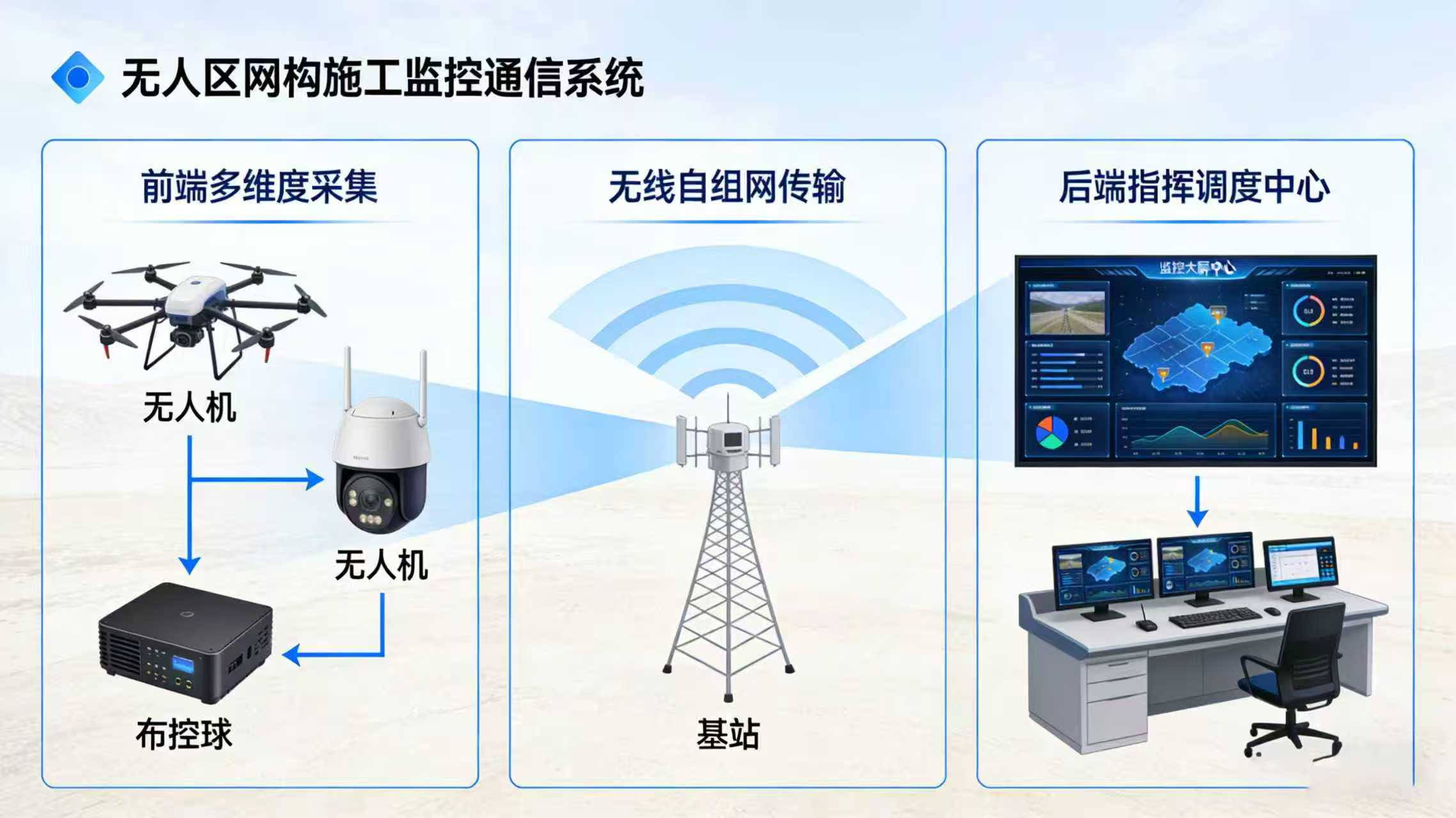
This solution adopts a “Layered Architecture, Centralized Control, Distributed Deployment” model, divided into 4 layers: Front-end Collection Layer (Monitoring + Communication Terminals), Mid-end Transmission Layer (Wireless Transmission Backbone Network), Back-end Control Layer (Monitoring & Communication Center), and Emergency Linkage Layer (Mobile + Voice Dispatch). Each layer works synergistically to form a closed-loop management system. The architecture design fits the core characteristics of no public network and mobile operations in uninhabited areas. All equipment uses industrial-grade products to adapt to harsh environments. The overall system architecture diagram is as follows:
[Image Placeholder 1: Overall Architecture Diagram of Monitoring and Communication System for Power Grid Construction in Uninhabited Areas] (Matches the style of the original link’s architecture diagram, labeling equipment at each level, data flow direction, core labels: Front-end Collection Layer, Mid-end Transmission Layer, Back-end Control Layer, Emergency Linkage Layer, clarifying equipment models and connection relationships at each layer, with a simple background color, highlighting the wireless transmission link)
Core Architecture Explanation
1. Front-end Collection Layer: Deployed at each construction point, responsible for video collection, personnel/equipment positioning, and voice terminal access. Core equipment is flexibly movable to adapt to the needs of scattered and frequently migrating construction points;
2. Mid-end Transmission Layer: The core consists of industrial-grade wireless bridges and Mesh Ad Hoc network equipment, building a wireless backbone network in an environment without public networks. It achieves long-distance, stable transmission of front-end data and supports multi-point signal relaying to solve terrain occlusion problems in uninhabited areas;
3. Back-end Control Layer: Deployed in the temporary construction command center (movable), responsible for video storage, image display, personnel/equipment control, and command issuance, achieving centralized control;
4. Emergency Linkage Layer: Through mobile APPs and handheld walkie-talkies, it achieves real-time linkage between field personnel and the command center, providing rapid response to emergencies and breaking spatial limitations.
III. Detailed Design and Implementation of Each Layer
This chapter is the core of the solution, clarifying equipment selection, deployment location, installation requirements, and debugging standards for each layer. Each link is optimized based on the construction scenario in uninhabited areas to avoid the difficulties of traditional solutions, ensuring that the construction team can implement it directly.
(I) Front-end Collection Layer (Flexible Deployment, Anti-Harsh Environment)
The front-end collection layer is the core of data sources, covering all key construction points. Combining the characteristics of scattered construction points, high mobility, and lack of mains power supply in uninhabited areas, it adopts a “Mobile Deployment + Solar Power Supply” model. The equipment uses industrial-grade, low-power, and sandstorm-resistant products. The specific design is as follows:
1. Point Planning (Fitting Actual Power Grid Construction, Blind-Spot-Free Coverage)
Based on the power grid construction process in uninhabited areas (Foundation Excavation → Tower Erection → Conductor Stringing → Equipment Acceptance), 5 types of core monitoring and communication points are planned. The specific distribution and uses are as follows:
| Point Type | Deployment Quantity (Per 10km Construction Section) | Deployment Location | Core Use | Deployment Characteristics |
|---|---|---|---|---|
| Foundation Excavation Point | 3-5 | Each tower foundation excavation site | Monitor excavation progress, construction standards, personnel safety | Temporary deployment, movable, no fixed point |
| Tower Erection Point | 2-3 per tower | Surrounding the tower erection site (unobstructed) | Monitor crane operation, tower verticality, personnel coordination | Temporary deployment, moved to the next tower after completion |
| Conductor Stringing Point | 4-6 | Start/end points of stringing, intermediate crossing points | Monitor stringing progress, crossing object protection, personnel operation | Combination of fixed + mobile, temporary deployment at crossing points |
| Material Storage Point | 1 | Centralized material storage area (near temporary command center) | Monitor material safety, entry/exit registration, anti-theft | Fixed deployment, unchanged throughout |
| Temporary Command Center Point | 1 | Center of the construction area (relatively convenient transportation) | Core control, personnel dispatch, emergency disposal | Fixed deployment, serving as the system’s core node |
2. Core Equipment Selection (Industrial-grade, Adapted to Harsh Environments in Uninhabited Areas)
All equipment is selected to be resistant to sandstorms, high/low temperatures, waterproof and dustproof (IP67 and above), and low power consumption, without relying on mains power. The specific selection and advantages are as follows:
(1) Monitoring Equipment
| Equipment Name | Selection Model (Reference Original Link) | Configuration Parameters | Advantages (Adapted to Uninhabited Areas) | Deployment Requirements |
|---|---|---|---|---|
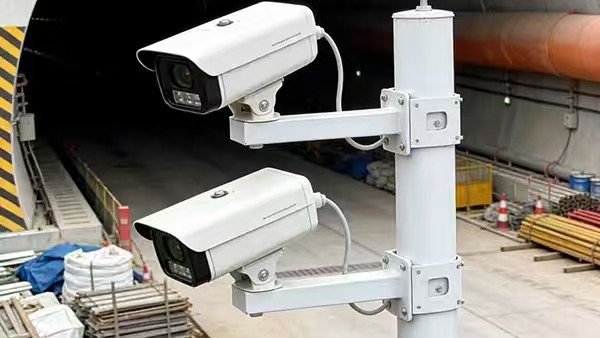
| HD IR Network Camera | Industrial-grade HD Dome Camera (Adapted for Mesh Transmission) | 1080P resolution, IR night vision distance ≥50m, supports PTZ control, motion detection, IP67 waterproof, low power consumption ≤15W | Resistant to sandstorms, high/low temperatures, normal monitoring at night, low power consumption adapted for solar power, PTZ control covering the full operation area | Mounted on a movable bracket, height 3-4m, unobstructed, facing the operation area |
| Panoramic Camera | 360° Panoramic Network Camera | 4K resolution, 360° blind-spot-free, supports motion detection alarm, IP67 waterproof | Single device covers the entire material storage area/surroundings of the command center, reducing the number of devices and O&M costs | Fixed installation at the center of the material area/roof of the command center, unobstructed |
(2) Communication and Positioning Equipment
| Equipment Name | Selection Model (Reference Original Link) | Configuration Parameters | Advantages (Adapted to Uninhabited Areas) | Deployment Requirements |
|---|---|---|---|---|
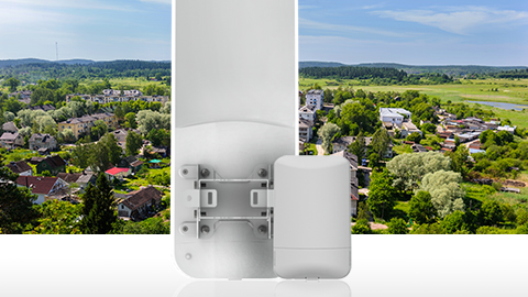
| Industrial-grade Mesh Ad Hoc Network Terminal | Outdoor Mesh Node (Supports Relay) | Operating frequency 5GHz, transmission distance 1-5 km, bandwidth ≥100Mbps, supports self-organizing network, relay, IP67 waterproof, low power consumption | No need for public network, automatic networking, supports multi-point relay, solves terrain occlusion and long-distance transmission problems in uninhabited areas, strong anti-interference capability | 1 unit deployed per construction point, mounted on top of the camera bracket, facing adjacent nodes unobstructed |
| Personnel Positioning Terminal | Handheld Positioning Walkie-talkie (Integrated Mesh Communication) | Supports GPS/Beidou dual-mode positioning, positioning accuracy ≤10m, supports voice call, emergency alarm, battery life ≥12 hours | Multi-purpose device, realizing personnel positioning and voice dispatch, one-key alarm for emergencies, adapted to signal-free environments in uninhabited areas | 1 unit per construction worker, carried at all times, charged regularly |
| Equipment Positioning Module | Industrial-grade GPS Tracker (Waterproof) | Supports GPS/Beidou positioning, real-time location upload, battery life ≥30 days, IP67 waterproof, accessible to monitoring platform | No wiring needed, directly attached to construction machinery, real-time monitoring of equipment location, preventing equipment loss and unauthorized movement | Attached to conspicuous positions on cranes, excavators, etc., avoiding obstruction |
(3) Power Supply Equipment (Core: Solving the Problem of No Mains Power in Uninhabited Areas)
Adopts an integrated “Solar Panel + Lithium Battery + Charge/Discharge Controller” power supply solution, independent of mains power, adapted to long-term construction in uninhabited areas. Specific selection is as follows:
- Solar Panel: 300W monocrystalline silicon, conversion efficiency ≥21%, resistant to sandstorms, high/low temperatures, adapted to lighting conditions in uninhabited areas;
- Lithium Battery: 12V/100Ah, large capacity energy storage, supports deep discharge, battery life ≥7 days (cloudy/rainy days), equipped with waterproof casing;
- Charge/Discharge Controller: Intelligent regulation, preventing overcharge and overdischarge, protecting battery life, supporting mains power backup (optional for temporary command center).
3. Front-end Deployment Implementation Steps
- Point Survey: Before construction, arrange personnel to survey each point, confirm unobstructed deployment positions, sufficient lighting (ensuring solar power supply), close to the operation area, and mark point coordinates;
- Bracket Installation: Use movable iron brackets (height 3-4m), installed at marked points. Brackets should be firmly fixed to prevent tipping due to sandstorms or strong winds (strong winds in uninhabited areas, bracket bases can be fixed with temporary concrete pouring);
- Equipment Installation: Install the camera and Mesh Ad Hoc terminal on the top of the bracket, with the camera facing the operation area and the Mesh terminal antenna facing adjacent points. Secure the equipment and tighten screws to prevent shaking;
- Power Supply System Installation: Install the solar panel on the side of the bracket (facing south, unobstructed). Place the lithium battery and charge/discharge controller in a waterproof distribution box, fixed at the bottom of the bracket. Ensure proper circuit connection and conduit protection to avoid sandstorm abrasion;
- Preliminary Debugging: Turn on the power, test the camera image, Mesh terminal signal, and positioning terminal connection to ensure equipment is working properly, with clear images and stable signals.
[Image Placeholder 2: Actual Scene of Front-end Collection Point Deployment for Power Grid Construction in Uninhabited Areas] (Matches the style of the original link’s real scene image, showing movable brackets, cameras, solar power systems, Mesh terminals, with a background of desert/mountainous terrain in uninhabited areas, labeling equipment names, clear image, highlighting the characteristics of industrial-grade equipment adapted to harsh environments)
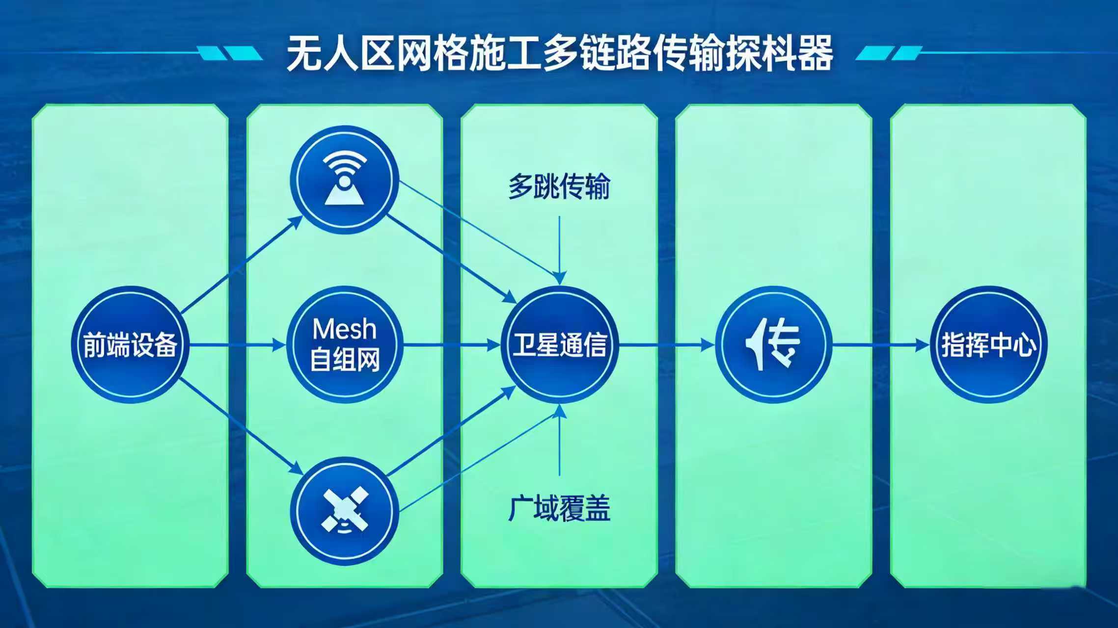
(II) Mid-end Transmission Layer (No Public Network, Long Distance, Stable Transmission)
The mid-end transmission layer is the “nerve center” of the system, aimed at solving transmission difficulties caused by no public network coverage and complex terrain (mountains, deserts, ravines) in uninhabited areas. It adopts the “Industrial-grade Mesh Ad Hoc Network + Wireless Bridge Relay” mode to build a wireless backbone network, realizing stable transmission of all front-end data (video, voice, positioning) to the back-end control center. The specific design is as follows:
1. Transmission Topology Design (Fitting Terrain of Uninhabited Areas, Avoiding Occlusion)
Combining the terrain characteristics of uninhabited areas (mountainous, ravines, prone to signal occlusion), a topology structure of “Core Node + Relay Node + Terminal Node” is adopted. The core node is deployed in the temporary command center, relay nodes are deployed on high ground (unobstructed), and terminal nodes are front-end equipment at various construction points. The specific topology is as follows:
- Core Node: 1 unit, deployed in the temporary command center, using a high-performance industrial-grade Mesh gateway, responsible for aggregating data from all relay nodes and terminal nodes, connecting to back-end control equipment;
- Relay Node: 2-3 units (per 10km construction section), deployed on high ground within the construction area (such as mountain tops, highlands), using industrial-grade wireless bridges (supporting relay mode), responsible for forwarding signals between terminal nodes and the core node to solve terrain occlusion problems;
- Terminal Node: 1 unit per construction point, i.e., the Mesh Ad Hoc network terminal deployed at the front end, responsible for collecting front-end data and transmitting it to the relay node or core node (unobstructed points can transmit directly to the core node).
[Image Placeholder 3: Wireless Transmission Topology Diagram for Power Grid Construction in Uninhabited Areas] (Matches the style of the original link’s topology diagram, clearly labeling Core Node, Relay Node, Terminal Node, marking equipment models, transmission distances, data flow direction, simplifying background to mark terrain (mountains, deserts), highlighting the role of relay nodes, clear and easy-to-understand links)
2. Core Transmission Equipment Selection
| Equipment Name | Selection Model (Reference Original Link) | Core Parameters | Advantages (Adapted to Uninhabited Areas) | Deployment Location |
|---|---|---|---|---|
| Industrial-grade Mesh Gateway (Core Node) | High-performance Outdoor Mesh Gateway | Operating frequency 5GHz, supports multi-node access (≥20 nodes), bandwidth ≥100Mbps, transmission distance ≤5km, IP67 waterproof, supports data encryption | Strong anti-interference capability, can simultaneously access multiple relay nodes and terminal nodes, stable data transmission, encrypted transmission prevents data leakage | Inside the temporary command center, fixed installation in a cabinet |
| Industrial-grade Wireless Bridge (Relay Node) | Outdoor Relay Bridge (Reference Original Link Model) | Operating frequency 5GHz, relay mode, transmission distance ≤3km, bandwidth ≥100Mbps, IP67 waterproof, resistant to sandstorms, high/low temperatures | Rapid deployment, no wiring needed, solves signal interruption caused by terrain occlusion, adapted for high-altitude deployment in uninhabited areas | Highlands, mountain tops within the construction area, mounted on fixed brackets |
| Mesh Ad Hoc Network Terminal (Terminal Node) | Same as Front-end Collection Layer Equipment | Supports self-organizing network, automatic connection to adjacent nodes, transmission distance ≤1-2km, low power consumption, movable | Flexible mobility, rapid re-networking after construction point migration, no re-debugging needed, adapted to mobile operation needs | Front-end brackets at each construction point |
3. Transmission Layer Deployment Implementation Steps (Key: Signal Debugging, Ensuring Stability)
- Relay Node Site Selection & Deployment: Survey the construction area, select high ground, unobstructed, wide-view locations as relay nodes. Install fixed brackets, mount wireless bridges on top, antenna facing core node and terminal node directions, ensure waterproofing and fixation;
- Core Node Deployment: Inside the temporary command center, install the Mesh gateway in the cabinet, connect to the back-end core switch and control PC, organize cables, and power on;
- Node Networking Debugging: Start all relay nodes, terminal nodes, and the core node. Equipment automatically forms a network. Debugging personnel use the control PC to check the connection status and signal strength of each node. Signal strength should be ≥-70dBm (ensure stable transmission);
- Signal Optimization: For nodes with weak signals, adjust antenna angles, change deployment locations, or add relay nodes to ensure all terminal nodes can stably connect to the core node, with video transmission free of lag and disconnection;
- Data Encryption Setting: Set encryption for all transmitted data, set access passwords to prevent unauthorized personnel from accessing the system and leaking construction data (power grid construction involves core facilities, data security is crucial).
4. Special Guarantee Measures for Transmission in Uninhabited Areas
- Anti-Sandstorm Protection: All transmission equipment antennas and interfaces are equipped with waterproof and dustproof covers. Interface connections are sealed with sealant to prevent sand from entering the equipment, damaging interfaces, and affecting signals;
- Anti-Interference Measures: Use 5GHz industrial frequency band, avoiding civilian 2.4GHz band (uninhabited areas may have herdsmen’s communication equipment, drone interference, etc.), and set independent channels to reduce co-channel interference;
- Backup Relay Scheme: In key transmission links (such as between the core node and key construction points), add 1 backup relay node to ensure that when the main relay node fails, the backup node can switch automatically without affecting transmission;
- Regular Inspection: Arrange O&M personnel to inspect relay node and core node equipment daily, check signal strength and equipment operating status, and timely clean sand and dust on equipment surfaces to ensure normal operation.
[Image Placeholder 4: Actual Scene of Relay Node Deployment for Power Grid Construction in Uninhabited Areas] (Matches the style of the original link’s real scene image, showing wireless bridges, brackets, and waterproof equipment deployed on mountain tops/highlands, with a panoramic background of the uninhabited area, labeling “Relay Node” and core functions, highlighting equipment characteristics of resistance to sandstorms and high/low temperatures)
(III) Back-end Control Layer (Centralized Control, Convenient Operation)
The back-end control layer is deployed in the temporary construction command center (movable prefab house) in the uninhabited area. It is the core control center of the entire system, responsible for front-end video storage, image display, personnel/equipment control, and command issuance. It achieves “Centralized, Visualized, and Convenient” management, adapted to the operating habits of construction management personnel, without the need for professional technical personnel. The specific design is as follows:
1. Control Center Equipment Configuration (On-demand Configuration, Cost-effective, Movable)
The control center equipment uses movable, miniaturized products, adapted to the spatial characteristics of the temporary command center (prefab house), while ensuring core functions. The specific configuration is as follows:
| Equipment Name | Configuration Quantity | Selection Requirements (Reference Original Link) | Core Function | Advantages |
|---|---|---|---|---|
| Control PC | 1-2 units | Industrial-grade Laptop (High/Low Temperature Resistant), Configuration ≥i5 Processor, 8G RAM, 512G SSD | Install monitoring and communication management platform, realize image viewing, personnel positioning, command issuance, fault troubleshooting | Movable, easy for management personnel to carry, adapted to temporary command center environment |
| Monitoring Monitor | 2-3 units (42 inch) | HD LCD Monitor, supports split-screen display, adapted for monitoring image display | Real-time display of all front-end monitoring point images, supports 1/4/9 split-screen switching, clear image | Miniaturized, small footprint, wall-mountable, saving command center space |
| NVR Video Recorder | 1 unit | Industrial-grade NVR, supports ≥16 channel video access, expandable HDD (≥4T), supports loop recording | Store all front-end surveillance videos, support video playback and retrieval, providing evidence for safety traceability and accident investigation | Waterproof and dustproof, adapted to uninhabited area environment, loop recording saves HDD space, no need for frequent replacement |
| Core Switch | 1 unit | Industrial-grade Fast Ethernet Switch, supports ≥8 ports, IP67 waterproof | Connect Mesh gateway, NVR, control PC, monitor, realizing equipment interconnection and data exchange | Resistant to harsh environments, sufficient ports, supporting later equipment expansion |
| Monitoring & Communication Management Platform | 1 set | Adapted to monitoring and communication needs in uninhabited areas, supports video monitoring, personnel positioning, voice dispatch, alarm linkage | Centralized control of all equipment, simple operation, clean interface, no professional technical training needed | Free upgrade, supports point addition and function expansion, fitting construction needs |
| UPS Backup Power | 1 unit | Capacity ≥1000VA, backup time ≥4 hours | Ensure normal operation of control center equipment during sudden power outages, preventing video loss and system interruption | Miniaturized, movable, adapted to unstable power supply issues in temporary command centers |
2. Core Functions
(1) Video Monitoring Function (Core)
- Real-time Preview: Supports real-time preview of video from all front-end points, free switching of single point image, split-screen display (1/4/9 split), clear image, no lag, no delay (latency ≤1 second);
- PTZ Control: Through the control PC, remotely control the shooting angle, focal length, and zoom of front-end dome cameras to achieve blind-spot-free viewing of the operation area;
- Video Storage and Playback: NVR supports 24-hour loop recording, recording storage time ≥30 days, allows retrieval of recordings by point, time, event (such as motion detection), supports local playback and export, providing evidence for accident investigation and safety traceability;
- Motion Detection Alarm: Front-end cameras detect abnormal movement (such as intrusion by unauthorized personnel, abnormal equipment movement), automatically trigger alarms, pop up alarm prompts on the control center monitor, play alarm sounds, and push alarm information to management personnel’s mobile terminals.
(2) Personnel Control Function
- Real-time Positioning: Through the management platform, view the location and trajectory of all construction personnel in real-time, positioning accuracy ≤10m, can label personnel names and positions, clearly grasping personnel distribution;
- Geo-fencing: Can set electronic fences in the construction area on the platform (such as dangerous areas, prohibited areas). Personnel violation of boundaries automatically triggers alarms, timely reminding management personnel;
- Voice Dispatch: Through the management platform, perform voice calls and group calls with single or multiple construction personnel, issue construction instructions and dispatch notifications, without the need for additional walkie-talkie base stations;
- Trajectory Tracking: Can query the movement trajectory of construction personnel in the past 7 days, understand personnel operation routes and operation duration, facilitating construction management and attendance statistics.
(3) Equipment Control Function
- Equipment Status Monitoring: Real-time view of the operating status of all front-end equipment (cameras, Mesh terminals, positioning modules), such as device online/offline, signal strength, power supply status, automatic alarm for equipment failure;
- Equipment Dispatch: Through the platform, remotely control the turning on/off of front-end equipment, such as idle point cameras and Mesh terminals, reducing power consumption and saving electricity;
- Fault Troubleshooting: The platform can display equipment failure reasons (such as power outage, signal interruption, equipment damage), facilitating O&M personnel to quickly locate faults and handle them in time, reducing fault troubleshooting time.
3. Control Center Deployment Implementation Steps
- Cabinet Installation: Inside the temporary command center, choose a dry, unobstructed location to install a small movable cabinet for placing the NVR, core switch, Mesh gateway, and UPS backup power;
- Equipment Installation: Install all control equipment into the cabinet in sequence, secure them, organize cables neatly, label them for easy maintenance later, and install UPS backup power at the bottom of the cabinet to avoid collision;
- Circuit Connection: Connect all equipment circuits in the order of “Mesh Gateway → Core Switch → NVR/Control PC/Monitor”, secure and protect circuits to avoid looseness and abrasion;
- Platform Installation and Debugging: Install the monitoring and communication management platform on the control PC, complete the docking of the platform with all front-end and back-end equipment, debug video preview, personnel positioning, voice dispatch functions, ensuring all functions are normal;
- Personnel Training: Conduct simple training (≤1 hour) for construction management personnel, explaining platform operation methods (video viewing, positioning query, instruction issuance, alarm handling), ensuring management personnel can operate independently.
[Image Placeholder 5: Actual Scene of Control Center in Temporary Command Center for Power Grid Construction in Uninhabited Areas] (Matches the style of the original link’s real scene image, showing monitors, control PC, cabinets, equipment inside the control center, management personnel operating the platform, labeling equipment names and core functions, highlighting centralized control and convenient operation)
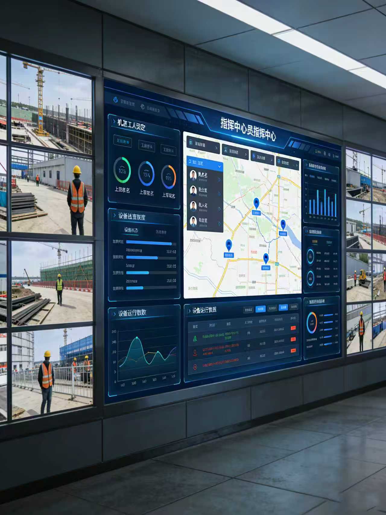
[Image Placeholder 6: Monitoring & Communication Management Platform Interface Screenshot] (Matches the style of the original link’s platform interface, clean interface, including video preview area, personnel positioning area, equipment status area, alarm prompt area, labeling functional modules, showing split-screen display, positioning trajectory, equipment status core functions, adapted to construction management personnel’s operation habits)
(IV) Emergency Linkage Layer (Rapid Response, Safety Guarantee)
Combining the emergency needs of power grid construction in uninhabited areas (personnel injury, equipment failure, sudden weather changes, intrusion by unauthorized personnel), the emergency linkage layer is built to realize a closed-loop management of “Alarm → Response → Disposal → Backtracking”, ensuring rapid disposal of emergencies and reducing safety risks. The specific design is as follows:
1. Emergency Linkage Equipment Configuration
- Mobile APP: Construction management personnel and site leaders install corresponding APPs on their mobile phones (supports Android, iOS), capable of receiving alarm information in real-time, viewing video, and issuing disposal instructions;
- Handheld Walkie-talkie: 1 unit per construction worker (same as front-end personnel positioning terminal, integrated walkie-talkie function), supports voice calling and emergency alarm;
- Emergency Alarm Button: Deploy emergency alarm buttons (waterproof, anti-accidental touch) at key construction points (such as tower erection points, foundation excavation points), personnel can trigger alarms with one click.
2. Emergency Disposal Process
- Alarm Triggering: Trigger emergency alarms through front-end camera motion detection, personnel boundary violation, emergency alarm buttons, or equipment failure;
- Alarm Push: The control center monitor pops up alarm prompts and plays alarm sounds, while simultaneously pushing alarm information (alarm type, alarm point, alarm time) to management personnel’s mobile APPs and handheld walkie-talkies;
- Rapid Response: Management personnel check the alarm point video within ≤1 minute after receiving the alarm, confirm the authenticity of the alarm (avoid false alarms), and clarify the alarm type and site situation;
- Instruction Issuance: Management personnel issue disposal instructions (such as arranging personnel for rescue, stopping construction, troubleshooting) through mobile APPs and walkie-talkies;
- On-site Disposal: Field personnel quickly go to the scene after receiving instructions, handle emergencies, and report disposal progress through walkie-talkies and APPs;
- Backtracking Summary: After disposal is completed, management personnel record the disposal situation on the platform, view on-site video playback, analyze the cause of the alarm, optimize prevention and control measures, and prevent recurrence of similar situations.
3. Emergency Guarantee Measures
- 24-Hour Duty: Arrange management personnel for 24-hour duty in the temporary command center to ensure timely response to sudden alarms (high risk in uninhabited area construction, unattended operation is not allowed);
- Backup Equipment: Equip 1-2 spare cameras, Mesh terminals, and positioning terminals. In case of sudden equipment failure, they can be quickly replaced to ensure normal system operation;
- Emergency Supplies: Equip first aid kits, emergency lighting, spare batteries, and other supplies in the control center and key construction points to deal with emergencies such as personnel injury and power outages.
[Image Placeholder 7: Schematic Diagram of Emergency Linkage Process for Power Grid Construction in Uninhabited Areas] (Matches the style of the original link’s flow chart, clearly showing the closed-loop process of “Alarm Triggering → Alarm Push → Rapid Response → Instruction Issuance → On-site Disposal → Backtracking Summary”, labeling the person responsible and time requirements for each link, simple and easy to understand, can be directly referred to for execution)
IV. Solution Guarantee Measures
To ensure the smooth implementation and stable operation of this solution in power grid construction scenarios in uninhabited areas, 4 guarantee measures are formulated combining the particularity of construction in uninhabited areas, covering equipment, construction, O&M, and personnel, comprehensively avoiding difficulties.
(I) Equipment Quality Guarantee
- All equipment is selected from industrial-grade products, meeting the requirements of sandstorm resistance, high/low temperature resistance, waterproof and dustproof in uninhabited areas, IP67 and above protection level, providing original factory warranty (≥1 year);
- Before equipment procurement, conduct sample testing to simulate harsh environments in uninhabited areas (high/low temperature, sandstorm), test equipment operation stability and transmission effect. Unqualified equipment will strictly not be purchased;
- During equipment transportation, ensure protective packaging to avoid transportation damage (inconvenient transportation in uninhabited areas, difficult to replace after damage). After arriving at the site, inspect equipment appearance and performance one by one.
(II) Construction Installation Guarantee
- Build a Professional Construction Team: Team members have experience in power grid construction in uninhabited areas and wireless monitoring and communication system installation, familiar with construction specifications in uninhabited areas, and can cope with complex terrain and harsh environments;
- Pre-construction Training: Conduct training for the construction team, explaining solution deployment requirements, equipment installation specifications, and safety precautions (high safety risks in uninhabited area construction, such as getting lost, sandstorms, low temperatures);
- Construction Process Control: Arrange personnel responsible for construction process control. After each point is installed, debug one by one to ensure equipment works normally. Immediate rectification for non-compliance;
- Construction Safety Guarantee: Construction personnel are equipped with professional protective equipment (safety helmets, sandstorm masks, cold-proof clothing), strictly abiding by safety specifications for construction in uninhabited areas to avoid safety accidents.
(III) O&M Guarantee (Core: Convenient O&M in Uninhabited Areas, Reducing Costs)
- Formulate Simple O&M Manual: Write an easy-to-understand O&M manual, clarifying daily inspection content, fault troubleshooting methods, and equipment maintenance processes. Construction personnel can handle simple faults by referring to the manual;
- Daily Inspection Mechanism: Arrange 1-2 O&M personnel to inspect all equipment daily (front-end points, relay nodes, control center), check equipment operating status, signal strength, power supply, and clean sand and dust on equipment surfaces;
- Rapid Fault Response: Establish a fault response mechanism. Simple faults (such as weak signal, equipment restart) are handled by O&M personnel within ≤1 hour; complex faults (such as equipment damage) involve contacting original factory technical personnel for remote guidance and replacing backup equipment to ensure the system is not interrupted;
- Power Supply Guarantee: Regularly check solar power systems and UPS backup power, clean dust on solar panel surfaces, ensure stable power supply, and avoid system interruption due to power outages.
(IV) Personnel Guarantee
- Personnel Configuration: Equip 1 system administrator (responsible for control center operation, system debugging), 1-2 O&M personnel (responsible for equipment inspection, fault disposal), and several construction personnel (cooperating with equipment installation, on-site operation);
- Training Guarantee: Train all relevant personnel. System administrators master platform operation and system debugging; O&M personnel master equipment maintenance and fault troubleshooting; construction personnel master equipment protection and emergency alarm methods;
- Responsibility System: Clarify the job responsibilities of each person, sign responsibility letters, ensure that equipment installation, system O&M, emergency disposal, and other tasks are responsible, avoiding shirking of responsibility.
V. Solution Cycle and Cost Budget
(I) Cycle
| Phase | Work Content | Time Required | Person Responsible |
|---|---|---|---|
| Preparation Phase | Equipment procurement, site survey, point marking, construction material preparation | 3-5 days | Project Manager |
| Installation Phase | Front-end point installation, relay node installation, control center installation | 2-3 days | Construction Team |
| Debugging Phase | System networking debugging, function debugging, personnel training | 1 day | System Administrator, Construction Team |
| Trial Operation Phase | System trial operation, troubleshooting potential faults, optimizing parameters | 1 day | System Administrator, O&M Personnel |
| Formal Operation Phase | System officially put into use, daily O&M, fault disposal | Throughout construction | All relevant personnel |
Note: Total cycle ≤10 days, can be flexibly adjusted according to the length of the construction section and the number of points, without affecting the power grid construction schedule.
(II) Cost Budget (Calculated per 10km Construction Section)
This solution uses cost-effective equipment, avoiding redundant configurations while ensuring system stability. The cost budget mainly includes equipment procurement costs, construction installation costs, and O&M costs. The details are as follows (reference price, can be adjusted according to actual needs):
| Cost Type | Core Included Content | Budget Amount (Reference) | Remarks |
|---|---|---|---|
| Equipment Procurement Cost | Front-end monitoring equipment, transmission equipment, control equipment, emergency equipment, power supply equipment | 150,000-200,000 RMB | Can be adjusted according to the number of points and equipment brands. Backup equipment can be selected as needed |
| Construction Installation Cost | Site survey, equipment installation, cable laying, debugging, personnel training | 30,000-50,000 RMB | Inconvenient transportation in uninhabited areas, can be adjusted according to construction difficulty |
| O&M Cost | Equipment maintenance, spare parts, O&M personnel salaries | 10,000-20,000 RMB/Month | Throughout construction, can be adjusted according to the number of O&M personnel |
| Total Budget | Equipment + Construction + O&M | 190,000-270,000 RMB + O&M Cost | Configurations can be optimized to reduce budgets (such as reducing backup equipment, choosing more cost-effective brands) |