WIFI6 11ax Series Wireless Bridge Motherboard PCBA: Core Hardware Analysis + Full-Scenario OEM Customization Solutions
In current long-distance wireless communication scenarios, wired cabling is limited by terrain, cost, and construction schedules, making it difficult to meet the high-frequency demands of security surveillance, campus networking, industrial IoT, and outdoor communication coverage extension. As the core equipment for achieving long-distance wireless data transmission, the performance, stability, and flexibility of a wireless bridge depend entirely on its internal core hardware—the wireless bridge PCBA mainboard. This article provides a deep dive into the technical principles, core performance, and application scenarios of the WIFI6 11ax series wireless bridge PCBA mainboard. It details the OEM customization service process and provides full-scenario implementation solutions to help industry practitioners, product developers, and procurement personnel fully understand the core value and application logic of this PCBA board, and how it serves as the “central hub” of the wireless communication link.
1. Introduction: Why is the PCBA Mainboard the Core of a Wireless Bridge?
The core function of a wireless bridge is to achieve Point-to-Point (PTP) and Point-to-Multipoint (PTMP) long-distance wireless data transmission, breaking the physical limitations of wired transmission. The realization of this function depends not on the casing or additional components of the finished device, but on its internal PCBA mainboard. It acts as the “brain + central nervous system” of the wireless bridge, integrating RF transmission/reception, data computing, network interfaces, protocol parsing, and other core functions. It is the key factor determining wireless transmission distance, rate, and stability.
The WIFI6 11ax series wireless bridge PCBA mainboard focused on in this article is core hardware designed for high-performance long-distance wireless communication. Distinct from traditional finished bridges, its core advantage lies in “customizability.” It supports OEM customization development, capable of adapting to the personalized needs of different industries and scenarios. We provide customers with full-process solutions from hardware design to software debugging, helping them quickly launch wireless bridge products that fit their market positioning.
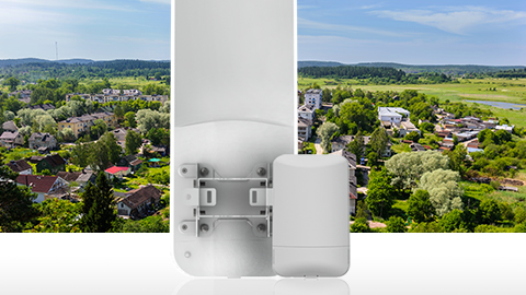
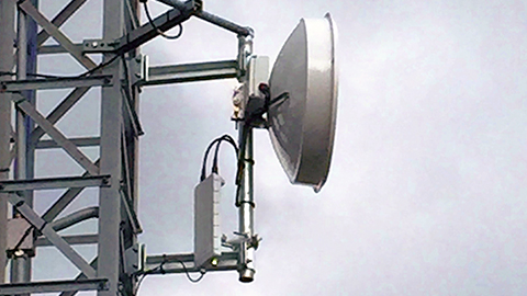
Image Suggestion: High-definition diagram of wireless communication link application scenarios, labeling core application scenarios (e.g., outdoor security surveillance, campus building networking, industrial plant data transmission, mountainous area communication coverage), using arrows to indicate data transmission direction, highlighting the core value of “wireless replacing wired”. Caption: Figure 1 Overview of Core Application Scenarios for Wireless Bridge PCBA
2. Core Cognition: What is the WIFI6 11ax Wireless Bridge PCBA Mainboard?
2.1 Definition and Core Positioning
The WIFI6 11ax series wireless bridge PCBA mainboard is a high-performance wireless communication core mainboard developed based on the IEEE 802.11a/n/ac/ax standards (WIFI6 technology). It is primarily used to assemble wireless bridge equipment, undertaking core tasks such as wireless signal transmission/reception, data processing, link control, and network adaptation. It is the core hardware carrier for PTP/PTMP wireless connections.
It must be clarified that this product is not a complete finished wireless bridge, but a customizable core PCBA mainboard. Customers can utilize OEM customization services to personalize hardware interfaces, software functions, frequency band adaptations, etc., based on their own needs. Combined with casings, antennas, and other components, it can be quickly assembled into finished wireless bridge products meeting specific industry requirements, significantly shortening product R&D cycles and reducing R&D costs.
2.2 Core Functions: The “Central Nervous System” of the Wireless Link
The role of the wireless bridge PCBA mainboard in the wireless communication link can be divided into four core dimensions, all indispensable, completely breaking the misconception that “PCBA is just a simple assembly of components”:
- Signal Transceiver Core: Through the integrated RF module, it receives and transmits wireless signals to achieve long-distance data transmission. The 5.1-5.8GHz version supports transmission up to 30km, while the 5.9-7.1GHz version adapts to specific frequency band requirements;
- Data Processing Core: Built-in dual-core processor rapidly parses and computes transmitted data, supporting throughput up to 1.5Gbps. This ensures real-time transmission of HD video and large-volume industrial data with no lag or latency;
- Network Adaptation Core: Equipped with 2.5Gbps + Gigabit dual Ethernet ports supporting PoE input/output. It can directly interface with cameras, switches, servers, and other devices, achieving “power + data transmission” integration and adapting to different network environments;
- Management & Scheduling Core: Through the built-in software system, it implements functions such as routing/bridge mode switching, security protocol control, spectrum analysis, and fault diagnosis, guaranteeing the stable operation of the wireless link and reducing post-maintenance costs.
2.3 Core Differences from Traditional Bridge Mainboards
Compared to traditional WIFI5 and older version wireless bridge mainboards, the core advantages of this product are concentrated in “technological generational upgrade + customization flexibility.” The specific differences are as follows, highlighting its market competitiveness:
| Comparison Dimension | Traditional Bridge Mainboard | WIFI6 11ax Series Bridge Mainboard PCBA |
|---|---|---|
| Wireless Standard | WIFI5 (802.11ac) and below | WIFI6 (802.11ax), backward compatible |
| Transmission Rate | Max 867Mbps Throughput | Max 1.5Gbps Throughput, 73% Increase |
| Transmission Distance | Generally ≤15km | Up to 30km (High Power + High Sensitivity) |
| Anti-Interference | Weak, prone to interference in high-density areas | Strong, OFDMA technology reduces multi-device interference |
| Customizability | Low, mostly standard products | High, supports full hardware/software/frequency OEM |
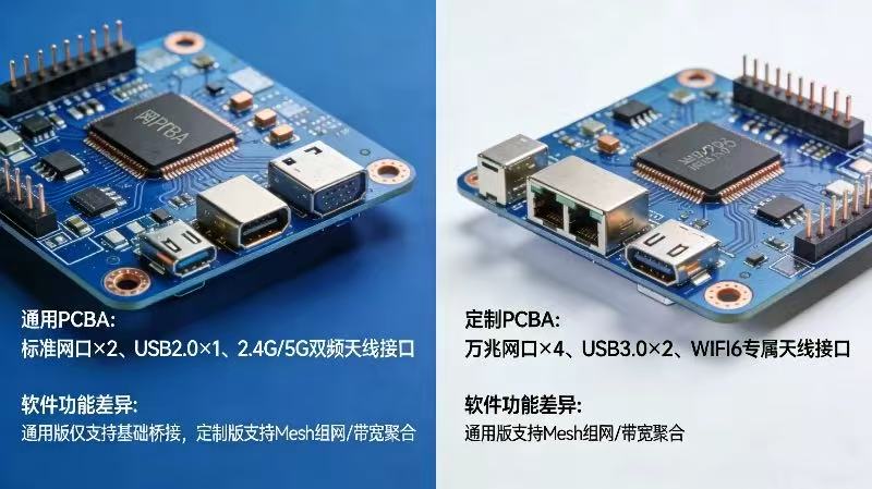
Image Suggestion: 1. Real photo of PCBA board (Front + Back, HD close-up), labeling core components (Dual-core processor, RF module, 2.5G port, MCX antenna interface, PoE interface). Caption: Figure 2 WIFI6 11ax Series Wireless Bridge PCBA Mainboard and Core Components; 2. Comparison photo of this product vs. traditional bridge mainboard, highlighting size and interface differences. Caption: Figure 3 Comparison of This Product and Traditional Bridge Mainboard
3. Deep Dive: Core Technology & Performance Parameters, Understanding the PCBA’s Hard Power
The performance of a wireless bridge PCBA mainboard fundamentally depends on its technical architecture and parameter configuration. This chapter analyzes the hard power of this product from three dimensions: technical principles, core parameters, and module breakdown. This allows readers to clearly understand “why it can achieve 30km long-distance and 1.5Gbps high-speed transmission” and how these technical advantages translate into actual application value.
3.1 Core Technology Analysis: WIFI6 Empowerment, Unlocking Long-Distance High-Speed Transmission
The core technological highlight of this product is the incorporation of WIFI6 (802.11ax) technology, combined with multiple high-performance transmission technologies, to build a stable and high-speed wireless communication link. The specific technical analysis is as follows, balancing professionalism and comprehensibility:
3.1.1 WIFI6 (802.11ax) Core Technical Advantages
As the next-generation wireless communication standard, WIFI6 offers significant advantages over the previous WIFI5: “High Rate, Low Latency, High Concurrency, Anti-Interference.” It is perfectly adapted to long-distance wireless transmission scenarios, specifically reflected in:
- 1024-QAM Modulation: Compared to WIFI5’s 256-QAM, modulation efficiency is increased by 25%. Under the same channel width, data transmission rate is significantly improved, achieving a single-stream rate of up to 1.2Gbps;
- 160MHz Channel Width: Supports a maximum 160MHz channel width, twice that of the traditional 80MHz channel. Data transmission bandwidth is doubled, effectively increasing throughput to meet HD video and large data volume transmission needs;
- OFDMA (Orthogonal Frequency Division Multiple Access): Divides the channel into multiple sub-channels, allowing simultaneous data transmission for multiple devices. This solves lag and latency issues during multi-device concurrent transmission, suitable for PTMP point-to-multipoint networking scenarios;
- TWT (Target Wake Time): Allows devices to enter sleep mode when not transmitting data, reducing power consumption. It also minimizes signal interference between devices, enhancing wireless link stability, suitable for outdoor low-power deployment scenarios.
3.1.2 2×2 MIMO RF Technology
The product adopts 2×2 MIMO (Multiple-Input Multiple-Output) RF mode, equipped with two transmitting antennas and two receiving antennas. The core advantages are “Increased Transmission Rate, Expanded Coverage Range, Enhanced Anti-Interference Capability”:
Compared to single-antenna designs, 2×2 MIMO uses spatial diversity technology to transmit two data streams simultaneously. This not only doubles the transmission rate but also effectively resists signal attenuation and interference. In outdoor long-distance transmission scenarios, even with terrain obstruction or electromagnetic interference, it ensures data transmission stability through multi-antenna signal reception. This is one of the core technical supports for achieving 30km long-distance transmission.
3.1.3 Dual-Band Adaptation Technology
The product is available in two frequency band versions, allowing flexible adaptation according to different regional regulations and application scenarios to meet personalized needs:
- 5.1-5.8GHz Version: Strong universality, adaptable to regulations in most regions globally. Supports up to 30km long-distance transmission, suitable for wide-range coverage scenarios like outdoor security, campus networking, and mountainous communication;
- 5.9-7.1GHz Version: Adapted to frequency band requirements of specific regions. Less interference and stronger transmission stability, suitable for industrial IoT and specialized communication scenarios requiring extremely high communication security and stability.
3.2 Full Analysis of Core Performance Parameters (with Parameter Table)
Parameters are the direct reflection of product performance. The following section details core parameters from four dimensions: wireless, hardware, software, and physical parameters, clarifying the practical application significance of each. A complete parameter table is provided for easy reference and comparison (highlighting differences between frequency versions):
3.2.1 Core Parameter Breakdown (Key Interpretations)
- Wireless Parameters: Supports IEEE 802.11a/n/ac/ax standards, 5.1-5.8GHz (30km) / 5.9-7.1GHz dual bands; Max Transmit Power +26dBm (adjustable per regional regulations), Receiver Sensitivity -96dBm (HE20, MCS0) to -55dBm (HE160, MCS11). Transmit power determines distance, receiver sensitivity determines anti-interference capability; the combination ensures long-distance transmission stability;
- Hardware Parameters: Built-in dual-core processor for fast operation and rapid processing of large data volumes; 1x 2.5Gbps Ethernet port (PoE Input) + 1x Gigabit Ethernet port (PoE Output, software controlled). 2.5G port meets high-speed data needs; PoE Input/Output achieves “Single Cable Power + Data Transmission,” eliminating extra cabling, suitable for outdoor power-scarce scenarios; MCX external antenna interface allows flexible pairing with different gain antennas to adjust distance and coverage;
- Software Parameters: Supports Bridge/IPv4/IPv6 Routing modes, adapting to different network architectures; DHCP Server/NAT/Static Routing/Port Forwarding for flexible networking configuration; 8 SSIDs per radio, supporting multiple device access; 802.1q VLAN & QnQ ensure data transmission security and isolation; Site Survey/Spectrum Analysis/Packet Analysis facilitate post-maintenance and troubleshooting; Supports WPA/WPA2/WPA3 security protocols to resist cyber attacks; Supports Web/Infinity Controller/SNMP v1/v2c/v3 management for remote control, reducing O&M costs;
- Physical Parameters: Dimensions 240mm×85mm×15mm, Weight 66g. Small and lightweight, easy to embed in various bridge casings; Power supply 24-48V, Max power consumption 15W/30W (with PoE Output enabled). Low power consumption fits outdoor solar power scenarios.
3.2.2 Complete Technical Parameter Table
| Parameter Category | Specific Parameter | 5.1-5.8GHz Version | 5.9-7.1GHz Version |
|---|---|---|---|
| Wireless Parameters | Wireless Standard | IEEE 802.11a/n/ac/ax (WIFI6) | |
| Frequency Band | 5.1-5.8GHz | 5.9-7.1GHz | |
| Transmit Power | Max +26dBm (adjustable per country/region) | ||
| Receiver Sensitivity | -96dBm (HE20, MCS0) ~ -55dBm (HE160, MCS11) | ||
| Channel Width | 20/40/80/160 MHz | ||
| Hardware Parameters | Processor | Dual-Core Cortex-A53 @ 1GHz | |
| Interfaces | 1x 2.5Gbps Ethernet (PoE In), 1x 1Gbps Ethernet (PoE Out) | ||
| Antenna Interface | 2x MCX | ||
| Physical Parameters | Dimensions & Weight | 240mm × 85mm × 15mm, 66g | |
| Power Supply | 24-48V Passive PoE | ||
| Operating Environment | Temperature: -40°C ~ +70°C; Humidity: 0~90% (Non-condensing) | ||
3.3 Core Module Breakdown: Understanding the PCBA’s “Internal Structure”
To give readers a more intuitive understanding of the PCBA board’s function, we break down its core modules, explaining the function of each and the logic of their collaborative work:
- RF Module: Primarily responsible for wireless signal transmission and reception. Integrates RF chips, power amplifiers, filters, and other components to convert digital signals into wireless signals for transmission, and convert received wireless signals into digital signals for processor handling. Core parameters like transmit power and receiver sensitivity are determined by this module, making it the core for long-distance transmission;
- Processor Module: Built-in dual-core processor, acting as the PCBA’s “brain.” Responsible for parsing and computing all transmitted data, controlling collaborative work among modules, and handling software functions like routing, bridging, and security protocols to ensure real-time and accurate data transmission, avoiding lag and latency;
- Network Interface Module: Includes 2.5Gbps and Gigabit Ethernet ports. Responsible for converting wired data to wireless data, interfacing with external devices (cameras, switches, servers, etc.). Supports PoE Input/Output to power itself and external devices, achieving “multi-use single cable” and simplifying cabling;
- Storage Module: Used to store software programs and configuration parameters. Ensures configuration information is not lost after power outage and allows rapid recovery to normal operation upon restart;
- Antenna Interface Module: MCX type external antenna interface for connecting external antennas. Allows pairing with different gain antennas based on application needs to adjust transmission distance and coverage, enhancing signal strength and anti-interference capability;
- Power Module: Responsible for converting input 24-48V voltage into working voltages required by each module. Ensures stable operation of all modules while controlling power consumption, suitable for low-power deployment scenarios.
Module Collaboration Logic: External devices (e.g., cameras) transmit wired data to the PCBA via the Ethernet port. The processor module parses the data and transmits it to the RF module. The RF module converts digital signals to wireless signals and transmits them via the external antenna. The receiving PCBA receives the wireless signal via antenna, the RF module converts it to digital, the processor parses it, and transmits it via Ethernet port to the receiving device (e.g., server), completing one data transmission. Simultaneously, the software system manages all modules in real-time via the processor, troubleshooting faults and ensuring security.
Image Suggestion: 1. Visual Chart of Technical Parameters (Bar/Line Graph), comparing throughput, transmission distance, and transmit power of this product vs. traditional bridge mainboards, visually highlighting advantages. Caption: Figure 4 Core Performance Comparison Chart; 2. PCBA Core Module Breakdown Diagram (labeling module names, locations, core functions). Caption: Figure 5 WIFI6 11ax Series Wireless Bridge PCBA Core Module Breakdown; 3. Module Collaboration Flowchart (arrows indicating data transmission and control logic). Caption: Figure 6 PCBA Module Collaboration Logic Diagram
4. Core Advantages: Why Choose This PCBA? (Differentiation + OEM Customization)
In the current wireless bridge PCBA market, product homogeneity is severe. The core competitiveness of this product lies in three aspects: “Ultra-High Performance + Full-Dimension OEM Customization + Strong Scenario Adaptability.” It meets high-performance communication needs while adapting to the personalized requirements of different industries, providing customers with differentiated competitive advantages. Core advantages are as follows:
4.1 Four Core Product Advantages (Hard Power Support)
Advantage 1: Ultra-High Performance, More Stable Long-Distance High-Speed Transmission
Powered by WIFI6 core technology, combined with 2×2 MIMO, 160MHz wide channel, and 1024-QAM modulation, it achieves a max throughput of 1.5Gbps. The 5.1-5.8GHz version supports up to 30km long-distance transmission. With max transmit power of +26dBm and excellent receiver sensitivity, it has strong anti-interference capabilities. Even in complex outdoor environments (terrain obstruction, electromagnetic interference), it ensures stable data transmission with no lag or packet loss, perfectly adapting to high-speed transmission needs like HD video and industrial big data.
Advantage 2: Dual-Band Adaptation, More Comprehensive Scenario Coverage
Available in 5.1-5.8GHz and 5.9-7.1GHz versions, flexibly selectable based on regional regulations and application scenarios. The 5.1-5.8GHz version has strong universality, suitable for wide-range outdoor networking, security surveillance, and mountainous communication. The 5.9-7.1GHz version offers less interference and higher stability, suitable for industrial IoT and specialized communication scenarios requiring high security and stability, covering the vast majority of long-distance wireless communication needs.
Advantage 3: Dual Port PoE Design, More Flexible Deployment
Equipped with 1x 2.5Gbps Ethernet port (PoE Input) and 1x Gigabit Ethernet port (PoE Output, software controlled). Supports “Power + Data Transmission” on a single cable, eliminating the need for extra power lines, significantly reducing outdoor deployment costs and time. It can directly interface with cameras, switches, and servers. PoE output can power external devices like cameras, simplifying network structure. The 2.5G port meets high-speed data transmission needs, adapting to future high-bandwidth scenario upgrades.
Advantage 4: Integrated Soft/Hard Management, More Efficient O&M
Built-in comprehensive software system supports Bridge/IPv4/IPv6 Routing modes, flexibly adapting to different network architectures. Supports Site Survey, Spectrum Analysis, and Packet Analysis for rapid fault diagnosis in wireless links, reducing post-maintenance difficulty. Supports Web, Infinity Controller, and SNMP management methods for remote device control and batch management, significantly improving O&M efficiency and reducing costs. Supports WPA/WPA2/WPA3 security protocols to secure data transmission and resist cyber attacks.
4.2 Core Competitiveness: Full-Dimension OEM Customization, Adapting to Personalized Needs
Compared to standardized PCBA mainboards in the market, the greatest advantage of this product is its support for full-dimension OEM customization. We can tailor the core mainboard to meet specific customer needs, industry requirements, and product positioning. This helps customers quickly launch differentiated products, shorten R&D cycles, and reduce R&D costs. Specific customization details are as follows (Key Highlights):
4.2.1 Hardware Customization (Core Customization Direction)
- Interface Customization: Adjust Ethernet port quantity and rate (e.g., adding Gigabit ports, adjusting PoE output parameters) based on customer needs to adapt to different external device connections; Change antenna interface type to fit specified antenna specifications;
- Size Customization: Adjust PCBA dimensions and component layout according to the customer’s finished bridge casing size, ensuring perfect fit without modifying the casing design;
- Power Consumption Customization: Optimize hardware design and adjust power parameters for deployment scenarios (e.g., solar power) to achieve low-power operation and extend power supply duration;
- Component Customization: Select different specification components (e.g., processors, RF chips) based on customer budget and performance needs to optimize cost while ensuring performance, or enhance specific performance (e.g., anti-interference).
4.2.2 Software Customization (Adapting to Customer Product Logic)
- Function Customization: Add or remove software functions based on customer needs, such as customizing exclusive routing protocols, adding specific security protection functions, or optimizing spectrum analysis tools to fit customer product logic;
- Protocol Adaptation: Adapt to customer-specified network protocols and communication protocols to ensure seamless interfacing between the PCBA mainboard and the customer’s other devices/systems, avoiding compatibility issues;
- Management Interface Customization: Customize the Logo, layout, and functional modules of the Web management interface to build an exclusive management interface and enhance brand recognition;
- Parameter Customization: Adjust wireless parameters (e.g., transmit power, channel width) based on customer needs to adapt to different regional regulations and application scenarios.
4.2.3 Frequency Band Customization (Region & Scenario Adaptation)
Customize exclusive frequency bands according to regional regulations and specific application scenarios. Beyond the existing 5.1-5.8GHz and 5.9-7.1GHz versions, other compliant bands can be adapted to ensure legal and compliant use locally, while optimizing band adaptability to reduce interference and improve transmission stability.
4.2.4 Customization Service Advantages (Core Customer Benefits)
- Shorten R&D Cycle: Professional R&D team provides full-process service from requirement communication to sample delivery. Customers need not invest massive R&D manpower and resources, significantly shortening product development cycles to seize market share quickly;
- Reduce R&D Costs: Rely on mature technical architectures to optimize customization schemes, avoiding repetitive R&D and reducing investment. Component selection can be optimized based on budget to control costs;
- Differentiated Competition: Customized design builds products fitting the customer’s market positioning, distinguishing them from standardized products and enhancing core competitiveness;
- Full-Process Technical Support: From requirement communication, scheme design, prototyping, test validation to mass production and post-maintenance, we provide full technical support to resolve issues during development and use.
Image Suggestion: 1. Mind Map of Product Advantages (Clearly presenting 4 Product Advantages + OEM Customization Advantages). Caption: Figure 7 Mind Map of WIFI6 11ax Series Wireless Bridge PCBA Core Advantages; 2. OEM Customization Service Content Diagram (Categorizing Hardware, Software, Frequency customization). Caption: Figure 8 Full-Dimension OEM Customization Service Content
5. Full-Scenario Application Solutions: How Does the PCBA Land? (Pain Points + Solutions + Customization)
The core value of a PCBA is ultimately reflected in actual application scenarios. This chapter combines PTP (Point-to-Point) and PTMP (Point-to-Multipoint) core transmission modes to break down solutions for four mainstream application scenarios. It clarifies pain points, networking methods, PCBA adaptation points, and corresponding OEM customization directions for each scenario, letting readers clearly understand the specific role of this PCBA board and “how to use it to solve actual communication problems.”
5.1 Scenario 1: Outdoor Security Surveillance Long-Distance Transmission Solution
Scenario Pain Points
In outdoor security surveillance scenarios (e.g., highways, scenic spots, oil fields, mines), monitoring points are dispersed and distant (mostly 5-30km). Complex terrain (mountains, hills) makes wired cabling costly, time-consuming, and hard to maintain. Some points lack power supply, increasing deployment difficulty. Real-time transmission of HD video (1080P/4K) requires high transmission rate and stability.
Networking Method
Adopt PTP + PTMP hybrid networking mode: Use the core monitoring center as the base, deploying 1 core receiving PCBA (with high-performance antenna). Deploy 1 transmitting PCBA (with camera, external antenna) at each monitoring point. Transmitters send video data to the core receiver via PTP. The core receiver aggregates data and transmits it to the monitoring center server. For close-range, multi-point areas, use PTMP mode where 1 receiving PCBA interfaces with multiple transmitting PCBAs to simplify structure.
PCBA Adaptation Points
- Use 5.1-5.8GHz version supporting up to 30km transmission to meet long-distance needs;
- Dual port PoE design: Transmitting PCBA powered via PoE Input, while PoE Output powers the camera, eliminating extra power lines and solving outdoor power issues;
- Max 1.5Gbps throughput supports real-time HD video (4K) transmission with no lag or packet loss;
- Strong anti-interference adapts to complex outdoor electromagnetic environments, ensuring video stability;
- Supports Site Survey and Spectrum Analysis for rapid fault diagnosis and reduced O&M difficulty.
OEM Customization Direction
Based on specific surveillance needs: 1. Hardware: Optimize power consumption for solar scenarios; add Gigabit ports for multiple cameras; 2. Software: Add video transmission optimization for stability; customize exclusive management interfaces for batch control; 3. Frequency: Adapt exclusive bands based on regional regulations to avoid interference.
5.2 Scenario 2: Campus/Enterprise Wireless Networking Solution
Scenario Pain Points
In campuses and enterprises (industrial parks, schools, office buildings), distances between buildings are significant (1-10km). Inter-connection and data sharing (office data, surveillance, device data) are required. Wired fiber is costly, disruptive, and slow to deploy. Some areas cannot be cabled (green zones, temporary structures) and need flexible networking. Network stability, security, and multi-device concurrency must be guaranteed.
Networking Method
Adopt PTMP (Point-to-Multipoint) mode: Use the campus core server room as the base, deploying 1 core receiving PCBA (with high-gain antenna). Deploy 1 transmitting PCBA at each building/plant, connecting to the building’s internal switch. This connects the building network to the core room. The core receiver connects to servers via Ethernet for campus-wide data aggregation. For temporary areas, portable transmitting PCBAs can be deployed for rapid access.
PCBA Adaptation Points
- Supports PTMP mode, 1 receiver to multiple transmitters, simplifying structure and reducing cost;
- 2.5G + Gigabit dual ports meet high-bandwidth needs for office data and HD video;
- WIFI6 technology supports multi-device concurrency, avoiding lag during simultaneous usage;
- Supports IPv4/IPv6 routing and 802.1q VLAN/QnQ for network isolation and office data security;
- Small and lightweight, easily embedded in wall-mounted bridge casings without damaging campus aesthetics.
OEM Customization Direction
Customizable: 1. Hardware: Adjust PCBA dimensions for campus bridge casings; increase ports for more switches; 2. Software: Customize campus network management systems for traffic statistics; add security features against external attacks; 3. Frequency: Adapt to regional bands to reduce interference and improve stability.
5.3 Scenario 3: Industrial IoT (IIoT) Data Transmission Solution
Scenario Pain Points
In IIoT scenarios (factories, power plants, chemical parks), equipment is dispersed and distant. Real-time data transmission (operation parameters, fault alerts) is needed. Strong electromagnetic interference requires extremely high stability and security, with zero tolerance for data loss or latency. Some equipment lacks power supply. Adaptation to industrial protocols for seamless interfacing with control systems is required.
Networking Method
Adopt PTP mode: Deploy 1 transmitting PCBA per industrial device to send data to the core receiving PCBA. The receiver connects to the industrial control server for real-time monitoring. For high-interference areas, use dual-band backup networking to ensure uninterrupted transmission. Transmitters use PoE power to solve power issues.
PCBA Adaptation Points
- Use 5.9-7.1GHz version for less interference and higher stability in strong electromagnetic environments;
- Stable core performance with excellent transmit power/sensitivity ensures real-time data transmission with no latency or loss;
- Supports industrial protocol adaptation for seamless interfacing with control systems;
- PoE Input/Output powers industrial devices, simplifying deployment;
- Supports WPA3 security to protect industrial data from leakage or tampering.
OEM Customization Direction
Customizable: 1. Hardware: Optimize anti-interference; adjust power for low-power devices; 2. Software: Adapt industrial protocols (Modbus, Profinet); add data encryption; customize fault alert functions; 3. Frequency: Adapt industrial bands to ensure interference-free transmission.
5.4 Scenario 4: Outdoor Communication Coverage Extension Solution
Scenario Pain Points
Remote areas, mountains, and rural zones often lack wired infrastructure and stable network coverage. Long-distance wireless links are needed for “blind spot coverage” (e.g., rural broadband, emergency comms). Harsh environments require high stability and protection. Lack of power requires low-power solar solutions.
Networking Method
Adopt PTP mode: Use the core base station as the base, deploying 1 core transmitting PCBA (with high-gain antenna). Deploy 1 receiving PCBA in the blind spot, connecting to user terminals (routers, phones) for coverage. For large areas, use multi-hop PTP for signal relay. Both ends use solar power.
PCBA Adaptation Points
- Use 5.1-5.8GHz version for up to 30km transmission to achieve long-distance coverage extension;
- Low power consumption fits solar supply needs;
- Strong anti-interference adapts to complex remote environments;
- Small and lightweight for rapid deployment in emergency scenarios;
- Supports bridge mode for seamless interfacing with core base stations.
OEM Customization Direction
Customizable: 1. Hardware: Optimize power for solar endurance; enhance protection for harsh environments; 2. Software: Add emergency comms optimization; customize coverage control functions; 3. Frequency: Adapt exclusive bands to expand coverage range.
Image Suggestion: 1. Networking Diagrams for each scenario (4 images), labeling PCBA location, data direction, and devices. Captions: Figure 9 Outdoor Security Surveillance Networking, Figure 10 Campus/Enterprise Networking, Figure 11 IIoT Data Transmission Networking, Figure 12 Outdoor Coverage Extension Networking; 2. Scenario Adaptation Table Chart, showing adapted versions and customization directions. Caption: Figure 13 PCBA Adaptation Table for Different Application Scenarios
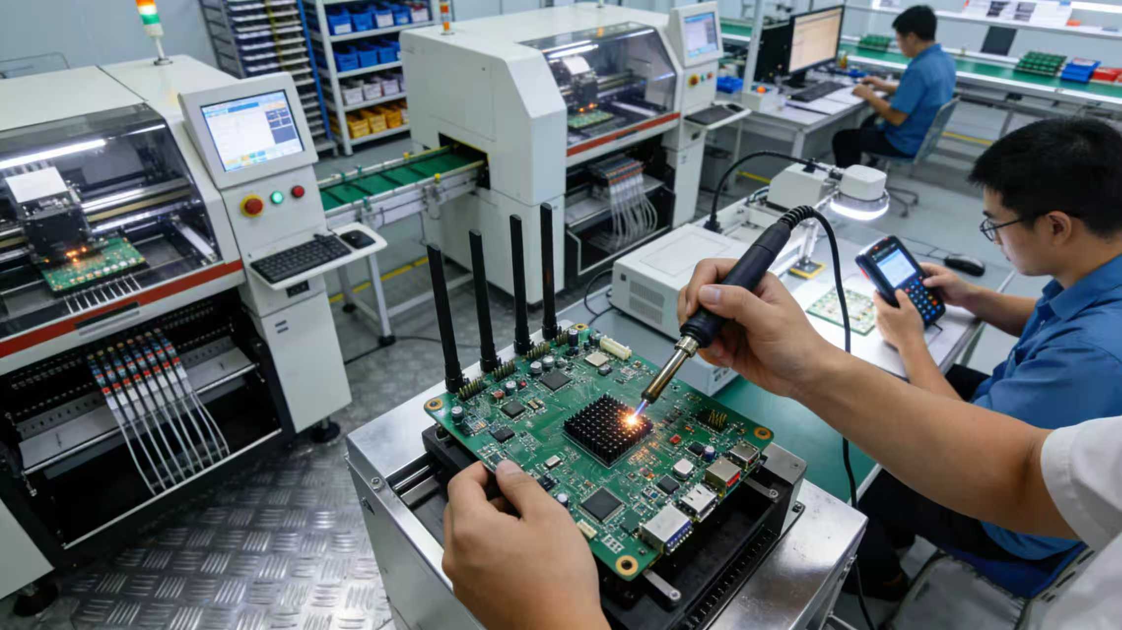
6. OEM Customization Service Detail: From Requirement to Mass Production, Full-Process Landing
To let customers clearly understand the OEM customization service flow and lower the threshold, this section details the process, core services, and advantages. It clarifies “what to do at each step from requirement to mass production,” ensuring an efficient and smooth customization process and the delivery of PCBAs that meet customer needs.
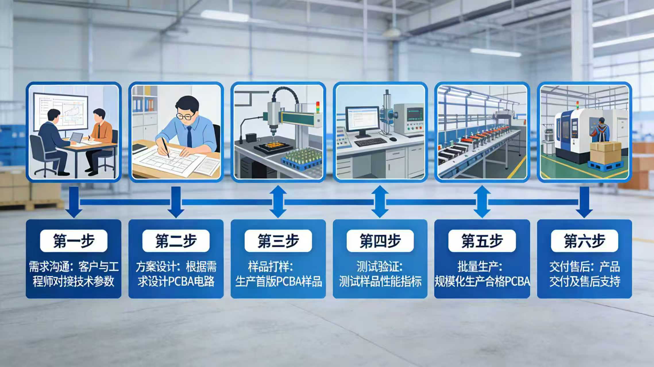
6.1 OEM Customization Service Core Process (6 Steps to Landing, Fully Controlled)
The service adopts a “Full-Process 1-on-1” mode, followed by a professional R&D team to ensure precise requirement implementation. The process is as follows:
- Requirement Communication (1-2 Working Days): Customer proposes specific needs (scenario, performance, hardware specs, software functions, frequency, budget, quantity). We arrange a dedicated project manager and R&D engineer to understand needs, confirm feasibility, and form a “Requirement Confirmation Document” for signature to avoid deviations.
- Scheme Design (3-5 Working Days): R&D team designs the customization scheme based on the document, including circuit design, component selection, software function design, and frequency adaptation. A “Customization Scheme Document” (drawings, parameters, function list, budget, cycle) is formed and submitted for review. Revisions are made until approval.
- Prototyping (5-7 Working Days): Upon approval, we start prototyping, strictly following the scheme to procure components, manufacture PCBAs, and debug software. Preliminary testing ensures compliance. Samples and “Sample Test Report” are sent to the customer for actual testing.
- Test Validation (3-5 Working Days): Customer tests samples in actual scenarios to verify performance, function, and adaptability. If modifications are needed, we quickly adjust and re-prototype/test until the sample passes validation and a “Sample Confirmation Document” is signed.
- Mass Production (7-15 Working Days, depending on quantity): Upon sample confirmation, mass production starts under strict ISO quality standards (procurement, welding, programming, testing). We provide regular progress updates. Final comprehensive inspection ensures every board meets quality requirements, and a “Mass Production Test Report” is issued.
- Delivery & Tech Support (1-2 Working Days): After production, delivery is made to the specified location. We provide full technical support (installation guide, debugging, troubleshooting, upgrades) and establish a long-term cooperation mechanism for future needs.
6.2 Customization Service Core Guarantees (Worry-Free)
- Technical Guarantee: Professional R&D team with rich experience in wireless PCBA customization solves technical challenges rapidly. Mature architecture ensures scheme feasibility and stability.
- Quality Guarantee: Strict ISO standards apply from procurement to mass production. Every step is controlled. All products come with quality reports and support third-party testing.
- Cycle Guarantee: Optimized process and clear delivery cycles ensure on-time delivery of samples and mass products. Urgent needs can be prioritized.
- Cost Guarantee: Scale procurement optimizes component costs. Schemes are optimized based on budget to control costs while ensuring performance.
- After-Sales Guarantee: Comprehensive service system with 1-on-1 support for timely response. Long-term support (upgrades, troubleshooting) ensures stable product operation.
6.3 Target Customers for Customization Service
This OEM customization service mainly adapts to the following three types of customers:
- Wireless Bridge Manufacturers: Need core PCBA mainboards to customize hardware/software fitting their product positioning, enabling rapid launch of differentiated finished bridges with reduced R&D time and cost;
- System Integrators: Need PCBA mainboards adapted to specific scenarios (security, industrial, campus) to seamlessly interface with their systems/equipment for project implementation;
- Specialized Communication Clients: Need PCBAs customized for specific industries/needs (emergency comms, private networks) with exclusive bands and functions.