High-Performance LigoWave Wireless Bridge Solution for 150km Long-Distance Power Grid Construction Projects
I. Solution Preface
This solution addresses the 150km wireless transmission requirements for high-altitude power grid construction projects (altitude ≥1500m), utilizing LigoWave PTP professional industrial bridges with a core “20km/hop” chain relay topology. It comprehensively resolves key challenges in high-altitude regions, including earth curvature, signal loss, and extreme environmental adaptation, while catering to real-time data transmission, video surveillance, and command dispatching needs for power grid construction. It fully complies with power grid construction safety regulations, providing a stable, efficient, and implementable wireless transmission solution for high-altitude power grid construction.
Core application scenarios: High-altitude mountain power grid transmission line construction, high-altitude substation construction, and remote high-altitude power grid inspection data transmission. It solves the challenges of difficult fiber optic deployment, high costs, and long construction periods in high-altitude areas. Leveraging the industrial-grade protection and anti-interference capabilities of LigoWave PTP equipment, it achieves stable 150km transmission, ensuring the continuity and safety of power grid construction.
II. Core Background and Requirements
2.1 Project Background
High-altitude power grid construction areas are primarily located in mountainous and plateau regions with complex terrain and significant altitude differences (typically 1500-4000m). Construction points are scattered, and there are no effective wired transmission links within 150km. Fiber optic deployment requires crossing mountains and valleys, presenting extremely high construction difficulties and potential damage to the high-altitude ecological environment, with construction periods unable to meet power grid construction schedule requirements. Additionally, high-altitude regions experience extreme weather conditions such as low temperatures, strong ultraviolet radiation, high winds, and thunderstorms, placing stringent demands on the protection level, anti-interference capability, and stability of wireless transmission equipment.
To address these challenges and align with the core requirements of “real-time performance, reliability, and safety” for power grid construction, LigoWave PTP industrial-grade wireless bridges are selected, employing a multi-hop relay solution with 20km/hop. This breaks through the limitations of high-altitude terrain and extreme environments, enabling stable transmission of construction data, high-definition video, and voice commands within a 150km range. It replaces traditional wired transmission methods, reducing construction costs, shortening construction periods, and adapting to the special scenarios of high-altitude power grid construction.
2.2 Core Requirements (Power Grid Construction)
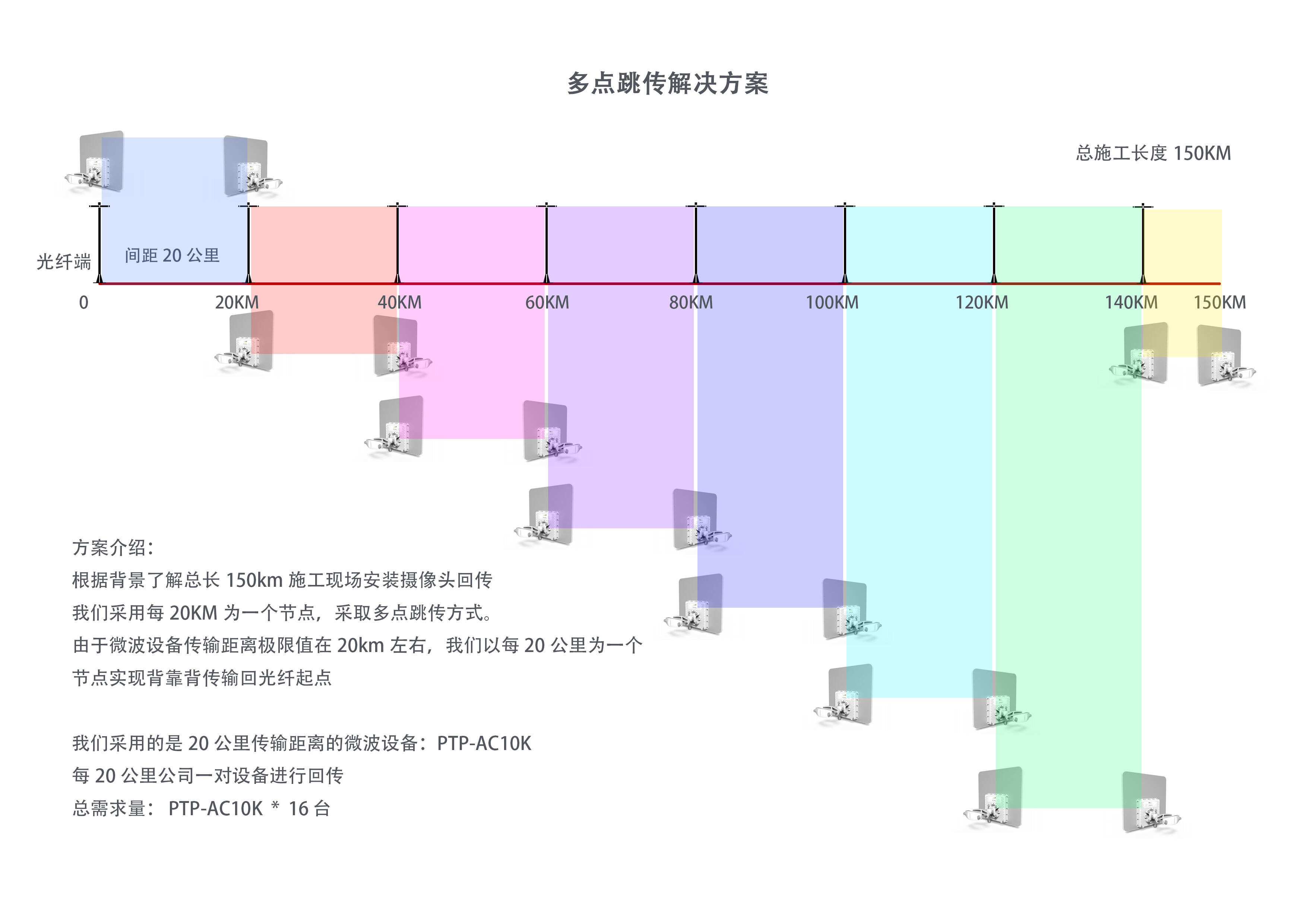
- Transmission distance: Total distance of 150km, using 20km/hop relay mode, with 7 hops total (including start point A, end point B, and 6 relay stations R1-R6). Each hop is strictly controlled within 20km to ensure transmission stability;
- Service requirements: Support real-time data for high-altitude power grid construction (construction equipment parameters, line monitoring data), over 10 channels of 1080P construction monitoring video, and voice command dispatching transmission without lag or packet loss;
- Environmental adaptation: Adapt to high altitude (1500-4000m), low temperature (-40℃~+70℃), strong ultraviolet radiation, level 12 high winds, thunderstorms, and other extreme environments. Equipment protection level ≥IP67, with lightning protection and electromagnetic interference resistance (adapting to strong electromagnetic environments in power grid construction);
- Stability: Annual availability ≥99.99%, single-hop interruption time ≤1 minute/month, total interruption time ≤7 minutes/year, meeting the 24-hour uninterrupted transmission requirements for power grid construction;
- Maintenance convenience: Support remote monitoring and parameter debugging, adapting to high-altitude unmanned relay stations to reduce maintenance costs;
- Compliance: Use 5.8GHz license-free frequency band (DFS channels), no need for additional frequency application, complying with national wireless transmission regulations and power grid construction safety standards.
III. Core Principles Explanation (Why Choose 20km/Hop?)
For 150km wireless transmission in high-altitude power grid construction, the core limiting factors include earth curvature, free space loss, Fresnel zone obstruction, and high-altitude extreme environmental interference. Combined with LigoWave PTP equipment parameters, 20km/hop represents the optimal choice for “stability, economy, and implementability” in high-altitude scenarios. The following details the core principles and limiting factors to help search engines recognize the professionalism of the solution.
3.1 Earth Curvature Issue
The Earth is approximately spherical, and wireless signals propagate in straight lines. During long-distance transmission, the Earth’s curvature causes the ground to bulge at the midpoint of the link, blocking the line of sight (LOS) and the first Fresnel zone. This is a core physical limitation for long-distance wireless transmission in high-altitude areas, where the impact of curvature is more pronounced due to significant altitude differences.
[Core Formula] (Including high-altitude atmospheric refraction correction, K=4/3, adapting to high-altitude thin air environment):
Midpoint curvature bulge height H = D²/(12.75×K) (D=single hop distance km, H=bulge height m);
Line-of-sight limit d_max=4.12×(√Ht+√Hr) (Ht/Hr=antenna height at both ends m).
[20km/Hop vs. Other Distance Comparison (High-Altitude Scenario)]:
- 20km/hop: Midpoint bulge H=20²/(12.75×1.33)≈23.5 meters. Combined with the high altitude of construction points (above 1500m), antennas only need to be elevated ≥15 meters to easily offset the curvature effect, avoid ground obstacles, and meet line-of-sight requirements. Engineering implementability is extremely high;
- 50km/hop: Midpoint bulge H≈147 meters. In high-altitude areas, additional high towers (≥150 meters) are required, resulting in high construction difficulty and costs. Moreover, in high-altitude high-wind environments, high towers pose safety risks and do not comply with power grid construction safety regulations;
- 150km single hop: Midpoint bulge≈1328 meters. Even at high-altitude points, antenna height would need to be ≥330 meters, which is impractical in reality. Additionally, signal loss is extremely high with no stability guarantee.
Conclusion: In high-altitude scenarios, 20km/hop minimizes the impact of Earth’s curvature, eliminating the need for additional ultra-high towers, adapting to the safety and cost requirements of power grid construction, and representing the optimal single-hop distance for 150km transmission.
3.2 Free Space Path Loss (FSPL) and Link Budget
Free space path loss is an unavoidable energy attenuation during wireless signal transmission, with the formula: FSPL(dB)=32.45+20lgf(GHz)+20lgd(km). In high-altitude areas with thin air, signal attenuation is slightly lower than in平原 areas, but single-hop distance must still be strictly controlled to ensure sufficient link budget.
[LigoWave PTP 20km/Hop Link Budget (High-Altitude 5.8GHz Scenario)]:
- Core parameters: LigoPTP 5 PRO (transmit power 29dBm), 30dBi parabolic antenna, 10MHz channel, feeder loss 2dB, high-altitude rain attenuation margin 15dB (low rainfall in high-altitude areas, rain attenuation impact negligible, margin reserved for extreme weather);
- Free space loss: FSPL=32.45+20lg5.8+20lg20≈122dB;
- Total gain: Transmit power 29dBm + transmit antenna 30dBi + receive antenna 30dBi – feeder loss 2dB = 87dB;
- Receive level: 87dB – 122dB = -35dBm;
- Signal-to-noise ratio (SNR): -35dBm – device receive sensitivity (-102dBm) = 67dB, far exceeding the reliable transmission standard of ≥35dB. The link margin is sufficient to withstand signal interference from extreme environments such as high-altitude high winds and thunderstorms.
Key note: LigoWave PTP equipment’s officially recommended reliable distance (meeting 50% throughput, 15dB margin) is ≤25km. 20km/hop falls within the optimal transmission range of the equipment, and combined with high-altitude environmental corrections, stability is significantly improved, fully meeting the high reliability requirements of power grid construction.
3.3 Fresnel Zone Obstruction
The first Fresnel zone is an “olive-shaped” space for signal transmission, where direct and reflected waves overlap. At least 60% of this zone must be unobstructed, otherwise signal attenuation, packet loss, or even interruption may occur. High-altitude areas have较多 trees, rocks, and mountains, so single-hop distance must be strictly controlled to reduce the difficulty of Fresnel zone clearing.
[First Fresnel Radius Formula] (midpoint): F1=17.3×√(D/(4f)) (D=single hop distance km, f=GHz, F1=radius m);
20km/hop (5.8GHz): F1=17.3×√(20/(4×5.8))≈13.5 meters;
Combined with the Earth’s curvature bulge of 23.5 meters, in high-altitude construction, it only requires ensuring no obstacles higher than 23.5+13.5=37 meters at the midpoint of the link. High-altitude construction points are mostly on mountain tops and highlands with fewer obstacles, making clearing difficulty low and eliminating the need for large-scale excavation, which aligns with high-altitude ecological protection and power grid construction schedule requirements.
If the single-hop distance exceeds 30km, the Fresnel radius will exceed 20 meters, requiring clearing height at the midpoint to exceed 50 meters, which is difficult to achieve in high-altitude mountainous areas and may damage the ecological environment, not complying with the “green construction” requirements of power grid construction.
3.4 High-Altitude Extreme Environment Adaptation Principles
High-altitude power grid construction faces issues such as low temperatures, strong ultraviolet radiation, high winds, thunderstorms, and strong electromagnetic interference (generated by power grid construction equipment). The core advantages of LigoWave PTP equipment’s industrial design are as follows, adapting to high-altitude scenarios:
- Low temperature adaptation: Adopts wide temperature design (-40℃~+70℃), avoiding device crashes and signal interruptions caused by low temperatures (below -30℃) in high-altitude winters;
- Protection adaptation: IP67 dust and water resistance, withstanding high-altitude heavy rain, snow, and hail, while resisting strong ultraviolet radiation to prevent equipment casing aging and performance degradation;
- Wind resistance adaptation: Small size and lightweight design, paired with high-strength mounting poles, can withstand level 12 high winds, adapting to high-altitude mountainous high-wind environments to avoid antenna deviation and equipment damage;
- Anti-interference adaptation: Supports DFS dynamic frequency selection, automatically avoiding electromagnetic interference generated by power grid construction equipment (transformers, welding machines, etc.), while using W-Jet 3 protocol to reduce signal interference in multi-hop relays, ensuring stable transmission;
- Lightning protection adaptation: Built-in lightning protection module, paired with external lightning protectors, grounding resistance <10Ω, withstanding high-altitude thunderstorm weather to avoid equipment damage from lightning strikes and ensure power grid construction safety.
IV. LigoWave PTP 150km (20km/Hop) Relay Solution Details
4.1 Topology Architecture (7-Hop Relay, 20km/Hop)
Core topology: Point A (construction start point/command center) → R1 (relay station 1) → R2 (relay station 2) → R3 (relay station 3) → R4 (relay station 4) → R5 (relay station 5) → R6 (relay station 6) → Point B (construction end point/monitoring point). Each hop is strictly controlled within 20km, with a total distance of 150km. A “chain PTP relay” mode is adopted, with each relay station deploying 2 LigoWave PTP bridges connected back-to-back (separate channels to avoid co-channel interference), adapting to the scattered point transmission requirements of high-altitude power grid construction.
Topology diagram (adapting to high-altitude power grid construction):
Point A (command center) ←PoE power supply→ LigoPTP RepidFire5-N+ 30dBi parabolic antenna ←20km line-of-sight→ R1 relay station (2 LigoPTP 5 RepidFire5-N back-to-back) ←20km line-of-sight→ R2 relay station (2 LigoPTP 5 RepidFire5-N back-to-back) ←20km line-of-sight→ R3 relay station (2 LigoPTP 5 RepidFire5-N back-to-back) ←20km line-of-sight→ R4 relay station (2 LigoPTP 5 RepidFire5-N back-to-back) ←20km line-of-sight→ R5 relay station (2 LigoPTP 5 RepidFire5-N back-to-back) ←20km line-of-sight→ R6 relay station (2 LigoPTP 5 RepidFire5-N back-to-back) ←20km line-of-sight→ Point B (construction end point/monitoring point) ←PoE power supply→ Construction monitoring/data collection equipment
Key note: Each relay station is located on high-altitude mountain tops or highlands, ensuring 100% line-of-sight with adjacent stations, no obstructions, and close proximity to power grid construction points for convenient construction data collection and transmission, reducing feeder length and signal loss.
4.2 Equipment Selection (All LigoWave Industrial Grade, Adapting to High-Altitude Power Grid Construction)
All equipment uses LigoWave professional-grade products, tailored to high-altitude extreme environments and power grid construction safety regulations. The equipment list is as follows (including quantity, parameters, and application scenarios):
(1) Core Bridge Equipment (16 units total, 2 units/hop)
Model: LigoPTP RepidFire 5-N or Mach5ac (outdoor industrial grade, high-altitude dedicated adaptation model)
Core parameters (adapting to high-altitude power grid construction):
- Frequency band: 5.8GHz (DFS license-free channels), automatically avoiding power grid electromagnetic interference, no frequency application required, complying with power grid construction compliance requirements;
- Transmit power: 29dBm (800mW), high-altitude thin air improves signal transmission efficiency, ensuring stable 20km transmission;
- Receive sensitivity: -102dBm (BPSK modulation), high sensitivity to receive weak signals, improving link margin and resisting high-altitude interference;
- Modulation: Supports BPSK/QPSK/64QAM, automatically switching to BPSK mode for long distances (20km) to reduce speed and ensure stability, adapting to real-time data transmission requirements for power grid construction;
- Protection level: IP67, dust and water resistant, resisting strong ultraviolet radiation and hail, adapting to high-altitude extreme weather;
- Operating temperature: -40℃~+70℃, handling high-altitude winter low temperatures and summer high temperatures;
- Protocol: W-Jet 3 (TDD time division duplex), low latency (single hop <5ms), strong anti-interference capability, adapting to multi-hop relays and ensuring smooth voice command and video transmission;
- Power supply: Industrial-grade PoE power supply (48V, 60W), supporting solar backup power supply, adapting to high-altitude non-utility relay station scenarios.
(2) Antenna Equipment (16 units total, 1 unit per bridge)
Model: 30dBi 1.2m parabolic antenna (5.8GHz, vertical polarization, high-altitude dedicated)
Core parameters (adapting to high-altitude power grid construction):
- Gain: 30dBi, high-gain design to compensate for slight signal transmission attenuation in high-altitude areas, improving receive level;
- Beamwidth: ≤3°, high-precision directional transmission, reducing signal spread and interference, adapting to precise alignment requirements for multi-hop relays;
- Aperture: 1.2m, wind-resistant design, paired with high-strength brackets to avoid antenna deviation caused by high-altitude high winds;
- Polarization: Vertical polarization, strict same polarization at both ends to avoid signal loss (different polarization can cause 3dB+ loss);
- Material: Corrosion-resistant, UV-resistant, adapting to high-altitude strong ultraviolet radiation and sand environment, extending service life.
(3) Supporting Equipment
- Feeder: 1/2″ ultra-soft low-loss coaxial cable, ≤30m per end, loss <0.5dB/m, reducing signal attenuation, joints treated with 7-layer waterproof tape + heat shrink tubing, adapting to high-altitude rain and snow environments;
- Mounting pole: 6m hot-dip galvanized high-strength pole, resisting level 12 high winds, adapting to high-altitude mountainous high-wind environments, fixed to concrete foundation at the bottom to ensure stability, complying with power grid construction safety standards;
- Lightning protection equipment: Antenna lightning protector, PoE lightning protector, 1 set per station, grounding resistance <10Ω, independent grounding grid, withstanding high-altitude thunderstorm weather to avoid equipment damage from lightning strikes;
- Power supply equipment: Industrial-grade PoE switch (1 per station), solar power supply system (for non-utility relay stations, including solar panels and batteries), ensuring 24-hour uninterrupted power supply, adapting to high-altitude unmanned scenarios;
- Protection enclosure: IP67 industrial-grade enclosure, 1 per station, for placing PoE switches and lightning protection equipment, dust and water resistant, low temperature resistant, protecting equipment safety;
- Debugging equipment: LigoWave dedicated debugging software, compass, GPS locator, for precise antenna alignment and parameter configuration, adapting to debugging needs in high-altitude complex terrain.
4.3 Channel Planning (Anti-Interference)
High-altitude power grid construction areas may have electromagnetic interference from other wireless devices and power grid construction equipment. Differentiated channel planning is adopted, with channel spacing ≥20MHz between hops, no overlap, and DFS dynamic frequency selection enabled to automatically avoid interference bands, ensuring stable transmission. Specific planning is as follows (5.8GHz DFS channels):
- A→R1: Channel 149 (5.745GHz)
- R1→R2: Channel 153 (5.765GHz)
- R2→R3: Channel 157 (5.785GHz)
- R3→R4: Channel 161 (5.805GHz)
- R4→R5: Channel 165 (5.825GHz)
- R5→R6: Channel 144 (5.720GHz)
- R6→B: Channel 140 (5.695GHz)
Key note: The 2 back-to-back bridges at each relay station use different channels to avoid co-channel interference. After enabling DFS functionality, the equipment can real-time monitor surrounding interference and automatically switch to interference-free channels, adapting to changing electromagnetic interference scenarios during power grid construction.
4.4 High-Altitude Site Selection and Installation Specifications
(1) Site Selection (A/B Points + 6 Relay Stations R1-R6)
Core site selection principles: Adapt to high-altitude power grid construction, considering line-of-sight, construction convenience, safety, and stability. Specific requirements are as follows:
- Line-of-sight requirement: Each adjacent station (A-R1, R1-R2…R6-B) must have 100% pure line-of-sight, no mountain, tree, or building obstructions, with over 60% of the first Fresnel zone unobstructed. This can be verified through Google Earth and on-site surveys to ensure signal transmission is not affected by obstructions;
- Altitude requirement: Site altitude ≥1500m, priority given to mountain tops and highlands along the power grid construction route. After antenna elevation, it can cover surrounding construction points, facilitating construction data collection while offsetting the effects of Earth’s curvature;
- Environmental requirement: Keep away from high-voltage lines and substations (electromagnetic isolation ≥50 meters) to avoid strong electromagnetic interference from power grid equipment; stay away from steep slopes and cliffs to ensure equipment installation and maintenance safety, complying with power grid construction safety regulations;
- Maintenance requirement: Relay stations prioritize locations with utility power; non-utility locations are equipped with solar power supply systems. Stations should be easily accessible for personnel to facilitate later debugging and maintenance, reducing high-altitude maintenance difficulty;
- Ecological requirement: Site selection should avoid damaging high-altitude vegetation and ecological environment, following the “green construction” concept to minimize impact on the surrounding environment.
(2) Installation Specifications (Ensuring Safety and Stability)
- Antenna installation: Antenna elevation ≥15 meters (top of mounting pole), alignment accuracy within ±0.5°, using compass and GPS locator for precise alignment, debugging to RSSI≥-65dBm, CCQ≥95%, fixed firmly to avoid deviation caused by high-altitude high winds; strict consistent antenna polarization (all vertical polarization) to avoid signal loss;
- Feeder installation: Feeder bending radius ≥20 times diameter, avoiding bending and damage, joints with waterproof treatment (7-layer waterproof tape + heat shrink tubing), feeder length ≤30m to reduce signal attenuation; feeder fixed to mounting pole to avoid wind-induced shaking causing joint loosening;
- Grounding installation: Antennas, mounting poles, protection enclosures, and lightning protection equipment all connected to an independent grounding grid, grounding resistance <10Ω, equipotential connection without breaks, withstanding high-altitude thunderstorm weather to avoid equipment damage from lightning strikes, complying with power grid construction lightning protection regulations;
- Equipment installation: Protection enclosures fixed to the middle of mounting poles (2-3 meters above ground) to avoid rainwater immersion and human damage; PoE switches and lightning protection equipment placed inside enclosures, wiring standardized with insulation treatment, adapting to high-altitude low-temperature and humid environments;
- Power supply installation: Utility power supply points use industrial-grade PoE power supply; non-utility points equipped with solar panels (power ≥300W) + batteries (capacity ≥100Ah) to ensure 72-hour uninterrupted power supply in rainy weather, adapting to high-altitude non-utility scenarios; power lines with anti-freeze and insulation treatment to avoid line damage from low temperatures.
4.5 Configuration Parameters
All LigoWave PTP bridges are uniformly configured, focusing on optimizing stability and anti-interference capabilities to adapt to high-altitude multi-hop relays and power grid construction service requirements. Specific parameters are as follows:
- Working mode: PTP Bridge (point-to-point bridging), AP mode disabled, focusing on data transmission;
- Channel bandwidth: 10MHz (optimal bandwidth for 20km/hop, reducing interference, improving stability, avoiding lag caused by high-altitude signal fluctuations);
- Modulation: Auto (automatic switching), automatically switching to BPSK mode for long distances, QPSK/64QAM mode for short distances, balancing bandwidth and stability;
- Transmit power: 27dBm (reduced by 2dB to avoid device self-excitation, improve stability, sufficient for 20km transmission in high-altitude environments);
- Anti-interference settings: Enable DFS dynamic frequency selection, enable anti-multipath interference function, adapting to electromagnetic interference environments in high-altitude power grid construction;
- Monitoring settings: Enable SNMP/WEB monitoring functions, real-time monitoring of RSSI, CCQ, temperature, voltage and other parameters, support remote alarm, facilitating maintenance of high-altitude unmanned stations;
- Encryption settings: Enable WPA2-PSK encryption to ensure the security of power grid construction data and monitoring video, prevent data leakage, complying with power grid construction confidentiality requirements.
V. Solution Performance and Service Carrying Capacity
5.1 Core Performance Indicators – Power Grid Construction Requirements
- Single-hop performance: Negotiated rate 300Mbps (10MHz channel), actual TCP throughput 80-120Mbps, latency <5ms, packet loss rate <0.1%;
- Total performance (7 hops): Total TCP throughput 40-60Mbps, total latency <35ms, packet loss rate <0.5%, meeting real-time transmission requirements for power grid construction;
- Stability: Annual availability ≥99.99%, single-hop annual interruption time ≤1 minute, total interruption time ≤7 minutes, capable of withstanding high-altitude low temperatures, high winds, thunderstorms and other extreme weather;
- Transmission distance: Each hop strictly controlled within 20km, total distance 150km, full line-of-sight transmission, no obstructions, stable signal;
- Maintenance convenience: Support remote debugging, parameter modification, status monitoring, relay stations can achieve unmanned operation, reducing high-altitude maintenance costs and difficulty.
5.2 Service Carrying Capacity
This solution can meet various service transmission needs for high-altitude power grid construction, adapting to command dispatching, safety monitoring, and data collection scenarios for power grid construction. Details are as follows:
- Video transmission: Supports real-time transmission of over 10 channels of 1080P construction monitoring video without lag or shadowing, enabling real-time monitoring of construction progress and safety status at high-altitude power grid construction points, ensuring construction safety;
- Data transmission: Supports real-time transmission of power grid construction equipment parameters, line monitoring data (such as conductor temperature, tower tilt), and construction progress data, with transmission latency <35ms, meeting real-time monitoring requirements for power grid construction;
- Voice transmission: Supports voice command dispatching, enabling real-time voice communication between point A command center, point B construction points, and construction personnel around each relay station, without noise or delay, ensuring efficient construction dispatching;
- Expansion capability: Can add monitoring and data collection equipment at construction points, supporting multi-device access, adapting to the point expansion needs of high-altitude power grid construction without large-scale topology adjustments.
VI. High-Altitude Power Grid Construction Adaptation Advantages
6.1 Strong Adaptation to High-Altitude Extreme Environments
The complete equipment adopts LigoWave industrial design, with IP67 protection, -40℃~+70℃ wide temperature range, resistance to level 12 high winds, lightning protection, and electromagnetic interference resistance, perfectly adapting to high-altitude low temperatures, strong ultraviolet radiation, thunderstorms, high winds and other extreme environments. It avoids construction interruptions caused by equipment failures, ensuring the continuity of power grid construction.
6.2 20km/Hop Relay, High Engineering Implementability
The 20km/hop design minimizes the impact of Earth’s curvature and Fresnel zone obstruction. Antenna elevation only requires 15 meters, eliminating the need for ultra-high towers, resulting in low construction difficulty and cost, adapting to the terrain characteristics of high-altitude mountains. It also avoids large-scale excavation, protecting the high-altitude ecological environment, and complying with the “green, safe, efficient” requirements of power grid construction.
6.3 Strong Business Adaptability for Power Grid Construction
The solution focuses on adapting to core businesses such as video surveillance, data collection, and voice command for high-altitude power grid construction, with low latency and low packet loss rate. It can meet the 24-hour uninterrupted transmission needs of power grid construction while supporting business expansion to adapt to different scales of high-altitude power grid construction projects.
6.4 License-Free Frequency Band, Convenient Compliance
Using 5.8GHz DFS license-free frequency band eliminates the need for additional frequency applications, saving approval time and enabling rapid deployment to adapt to the tight construction schedules of power grid projects. It also complies with national wireless transmission regulations and power grid construction compliance requirements.
6.5 Convenient Maintenance, Reducing High-Altitude Maintenance Costs
Support for remote monitoring and debugging allows relay stations to achieve unmanned operation, eliminating the need for frequent personnel travel to high-altitude sites, reducing the labor intensity and safety risks for maintenance personnel, while reducing maintenance costs, adapting to the maintenance needs of power grid construction in high-altitude uninhabited areas.
VII. Solution Feasibility Conclusion
The LigoWave PTP 150km wireless transmission solution (20km/hop, 7-hop relay) is fully adapted to the scenario requirements of high-altitude power grid construction projects. The core conclusions are as follows:
- Technically feasible: The 20km/hop relay design completely solves core issues such as Earth’s curvature, Fresnel zone obstruction, and signal loss in high-altitude areas. The link budget is sufficient, equipment adapts to high-altitude extreme environments, and stability and reliability meet the 24-hour uninterrupted transmission requirements for power grid construction;
- Engineering feasible: No need for ultra-high towers, site selection and equipment installation comply with the terrain characteristics of high-altitude mountains, construction difficulty is low, construction period is short, rapid deployment is possible, adapting to the schedule requirements of power grid construction while protecting the high-altitude ecological environment;
- Economically feasible: Compared to traditional fiber optic deployment (fiber optic deployment costs in high-altitude areas are approximately 500,000-800,000 yuan/150km), this solution has a lower budget and lower maintenance costs, significantly reducing transmission costs for high-altitude power grid construction;
- Compliance feasible: Using 5.8GHz license-free frequency band, complying with national wireless transmission regulations and power grid construction safety standards, service carrying capacity meets power grid construction needs, and can be widely applied to high-altitude mountain power grid transmission line construction, substation construction and other scenarios.
In summary, this solution is the optimal solution for 150km wireless transmission in high-altitude power grid construction. Relying on the advantages of LigoWave PTP professional-grade equipment and combining with the 20km/hop relay topology, it achieves stable, efficient, and low-cost wireless transmission, helping high-altitude power grid construction progress smoothly.
VIII. Alternative Solutions and Risk Response
8.1 Alternative Solutions (Adapting to Special Scenarios)
- Scenario 1: Line-of-sight cannot be achieved at some stations → Use LigoWave PTP industrial bridges that support non-line-of-sight transmission, adapting to severely obstructed points in high-altitude mountains, maintaining 20km/hop to ensure stable transmission;
- Scenario 2: Extremely high bandwidth requirements (>100Mbps) → Select LigoPTP RepidFile 6-N (6GHz frequency band) to increase single-hop throughput, maintaining 20km/hop to meet high bandwidth requirements, but costs will increase by approximately 20%;
- Scenario 3: No relay station location points → Use 10GHz+ licensed microwave bridges, single-hop up to 50km, reducing the number of relay stations, but requiring frequency application, higher costs (approximately 3 times that of this solution), and longer approval cycles, only as an alternative solution.
8.2 Risk Response (High-Altitude Power Grid Construction Focus)
- Risk 1: Antenna deviation caused by high-altitude high winds → Use high-strength mounting poles, strengthen antenna fixation, conduct regular inspections (once per quarter), timely adjust antenna alignment angles, and enable remote monitoring to real-time monitor signal status;
- Risk 2: Device crashes caused by high-altitude low temperatures → Select wide-temperature equipment, provide thermal insulation for device enclosures, regularly check power supply systems to avoid power interruptions caused by low temperatures;
- Risk 3: Equipment damage caused by thunderstorm weather → Improve lightning protection systems, regularly test grounding resistance (once every six months) to ensure good grounding, and enable device lightning protection mode before thunderstorm weather;
- Risk 4: Signal interruption caused by electromagnetic interference from power grid construction → Enable DFS dynamic frequency selection, real-time monitor interference, automatically switch channels, and optimize site selection away from high-voltage lines and substations;
- Risk 5: Power interruption at non-utility relay stations → Configure large-capacity solar power supply systems (battery capacity ≥100Ah), regularly check solar panel and battery status to ensure 72-hour uninterrupted power supply in rainy weather.
IX. Common Questions about Wireless Transmission for High-Altitude Power Grid Construction (FAQ)
1. Why choose wireless transmission solutions for high-altitude power grid construction?
High-altitude areas have complex terrain, making fiber optic deployment difficult, costly, and time-consuming, while also easily damaging the ecological environment. Wireless transmission solutions require no excavation, enable rapid deployment, effectively address communication needs for high-altitude power grid construction, and reduce construction costs and environmental impact.
2. What are the advantages of the 20km/hop relay solution in high-altitude areas?
The 20km/hop design minimizes the impact of Earth’s curvature, requiring only 15 meters of antenna elevation without the need for ultra-high towers, resulting in low construction difficulty and cost. Additionally, it reduces the difficulty of Fresnel zone clearing, adapts to high-altitude mountain terrain, and complies with green construction requirements.
3. How do LigoWave PTP devices adapt to high-altitude extreme environments?
LigoWave PTP devices adopt industrial-grade design with IP67 protection, -40℃~+70℃ wide temperature range, resistance to level 12 high winds, lightning protection, and electromagnetic interference resistance, perfectly adapting to high-altitude low temperatures, strong ultraviolet radiation, thunderstorms, high winds and other extreme environments.
4. What service requirements can the bandwidth of wireless transmission for high-altitude power grid construction meet?
Using the 7-hop relay solution with LigoWave PTP devices, the total TCP throughput can reach 40-60Mbps, supporting over 10 channels of 1080P construction monitoring video, real-time data transmission, and voice command dispatching, meeting the multi-service requirements of power grid construction.
5. How is the stability of wireless transmission in high-altitude areas ensured?
By strictly controlling single-hop distance (within 20km), ensuring line-of-sight transmission, optimizing site selection and installation specifications, and combining with the industrial-grade protection and anti-interference capabilities of LigoWave PTP devices, annual availability ≥99.99% can be achieved, with single-hop annual interruption time ≤1 minute.
6. What are the advantages of 5.8GHz license-free frequency band in high-altitude power grid construction?
The 5.8GHz DFS license-free frequency band eliminates the need for additional frequency applications, saving approval time and enabling rapid deployment to adapt to the tight construction schedules of power grid projects. It also complies with national wireless transmission regulations and power grid construction compliance requirements.
7. What factors should be considered for high-altitude wireless transmission site selection?
Site selection should ensure line-of-sight transmission, avoid obstacles, ensure equipment safety, facilitate construction and maintenance, while considering factors such as altitude, terrain, power supply, and ecological environment to ensure stable station operation and construction safety.
8. How to solve power supply issues for non-utility relay stations?
Solar power supply systems can be configured, including solar panels, batteries, and charge controllers, to ensure 24-hour uninterrupted power supply for equipment. Additionally, regularly check the status of the solar system to ensure normal operation even in rainy weather.
9. What impact does high-altitude high wind have on wireless transmission equipment? How to respond?
High-altitude high winds may cause antenna deviation and equipment damage. Response measures include: using high-strength mounting poles, strengthening antenna fixation, conducting regular inspections to adjust antenna angles, and enabling remote monitoring to real-time monitor signal status.
10. What are the latency and packet loss rates of wireless transmission for high-altitude power grid construction?
Using the 7-hop relay solution, total latency is <35ms, and packet loss rate is <0.5%, which can meet the requirements for real-time data transmission, video surveillance, and voice command in power grid construction, ensuring efficient construction dispatching.
11. How to solve lightning protection issues in high-altitude areas?
By improving lightning protection systems, including built-in lightning protection modules in equipment, external lightning protectors, good grounding systems (grounding resistance <10Ω), regularly testing grounding resistance, and enabling equipment lightning protection mode before thunderstorm weather.
12. How scalable is the wireless transmission solution for high-altitude power grid construction?
The solution supports business expansion, allowing for the addition of monitoring and data collection equipment at construction points, supporting multi-device access, adapting to the point expansion needs of high-altitude power grid construction without large-scale topology adjustments.
13. How to remotely monitor and manage high-altitude wireless transmission equipment?
LigoWave PTP devices support remote monitoring, parameter debugging, and status monitoring, which can be achieved through web interfaces or management software for remote device management, eliminating the need for frequent personnel travel to high-altitude sites and reducing maintenance costs.
14. How to solve signal interference in high-altitude wireless transmission?
By enabling DFS dynamic frequency selection to real-time monitor interference and automatically switch channels, while optimizing site selection away from high-voltage lines, substations, and other strong electromagnetic interference sources to ensure stable signal transmission.
15. What is the cost of wireless transmission solutions for high-altitude power grid construction?
Compared to fiber optic deployment, wireless transmission solutions have lower costs, require no excavation, save material and labor costs, and have faster deployment speeds, allowing for quick put-into-use and adapting to the tight construction schedules of power grid projects.
16. How to ensure line-of-sight requirements for high-altitude wireless transmission?
Through preliminary planning with Google Earth, on-site survey verification, and optimized site selection, ensure 100% pure line-of-sight between each adjacent station, no mountain, tree, or building obstructions, and over 60% of the first Fresnel zone unobstructed.
17. What impact does high-altitude low temperature have on device batteries? How to respond?
High-altitude low temperatures can reduce battery capacity and lifespan. Response measures include: selecting batteries with good low-temperature performance, configuring thermal insulation measures, regularly checking battery status, and ensuring normal charging of the solar system.
18. What are the acceptance criteria for wireless transmission solutions for high-altitude power grid construction?
Acceptance criteria include: meeting transmission distance requirements, bandwidth and latency meeting business needs, stable equipment operation, standardized site installation, qualified lightning protection and grounding systems, normal remote monitoring functions, etc.
19. How to handle sudden failures in high-altitude wireless transmission?
Establish a fault emergency response plan, including remote diagnosis, rapid response mechanisms, and standby equipment preparation. Through remote monitoring, promptly detect faults, locate problem areas, and take corresponding measures to quickly restore transmission.
20. What is the maintenance cycle for wireless transmission solutions for high-altitude power grid construction?
Recommended maintenance cycles are: daily remote monitoring (daily), regular inspections (quarterly), and comprehensive maintenance (semi-annually), including equipment status checks, antenna angle adjustments, lightning protection system testing, and power supply system maintenance.